Eureka AIR delivers breakthrough ideas for toughest innovation challenges, trusted by R&D personnel around the world.

Anterior part of a nacelle of an aircraft propulsion unit having a shock absorbing element

Active Publication Date: 2019-06-27
AIRBUS OPERATIONS SAS
View PDF0 Cites 10 Cited by
  • Summary
  • Abstract
  • Description
  • Claims
  • Application Information

AI Technical Summary

Benefits of technology

The patent is about a new solution to connect the external panel and internal structure of a large nacelle, and to absorb any deformations that might occur. A shock-absorbing element is placed between the rigidifying frame and the internal structure of the nacelle to protect the connection and absorb any shocks or accidents. This element can deform under the impact of an impact to absorb the energy of the impact and protect the rear bracket. The technical effect is to provide better protection for the nacelle and its components in the event of a shock or impact.

Problems solved by technology

For example, birds or foreign objects may collide with the aircraft, and notably with one of the propulsion units thereof.
These collisions may damage the propulsion units.
In the most serious circumstances, a blade breakage may occur.
This has negative impacts on the weight and cost of manufacture of the frames.
It can be seen that the configuration of the anterior part of a nacelle used in the prior art is not perfectly suited to use for such a propulsion unit of UHBR type or, more generally, for a propulsion unit that has a nacelle of large diameter.

Method used


Image

  • Anterior part of a nacelle of an aircraft propulsion unit having a shock absorbing element
  • Anterior part of a nacelle of an aircraft propulsion unit having a shock absorbing element
  • Anterior part of a nacelle of an aircraft propulsion unit having a shock absorbing element

Examples


Embodiment Construction

[0050]Some embodiments will now be described with reference to the Figures.

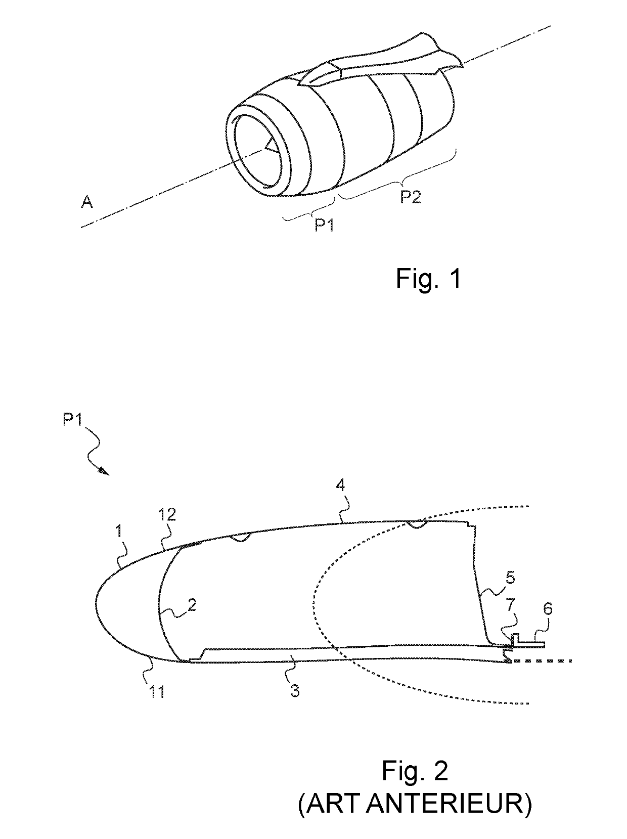
[0051]FIGS. 1 and 2, which respectively show general features of aircraft propulsion units and a nacelle anterior part configuration according to the prior art, were described hereinabove.

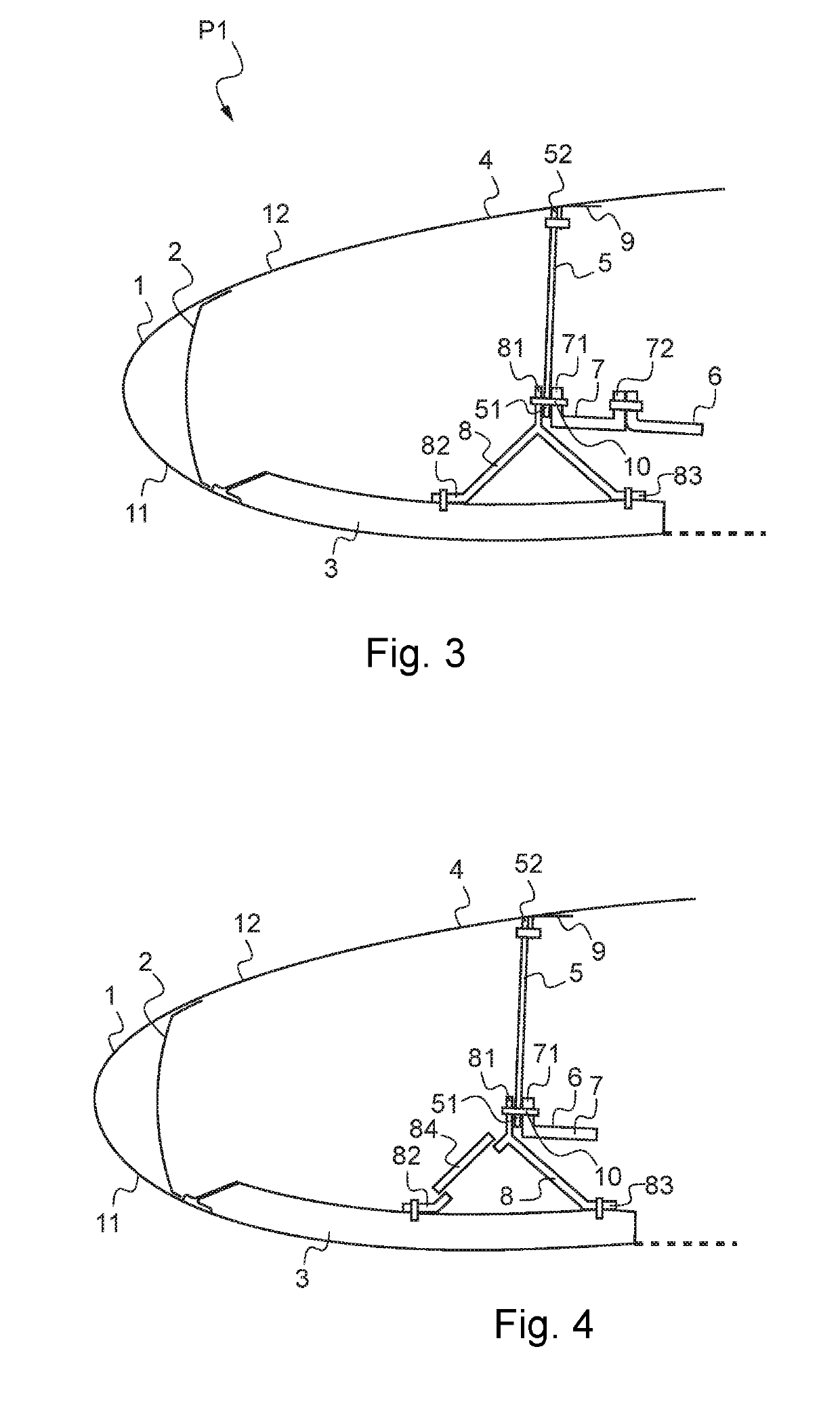
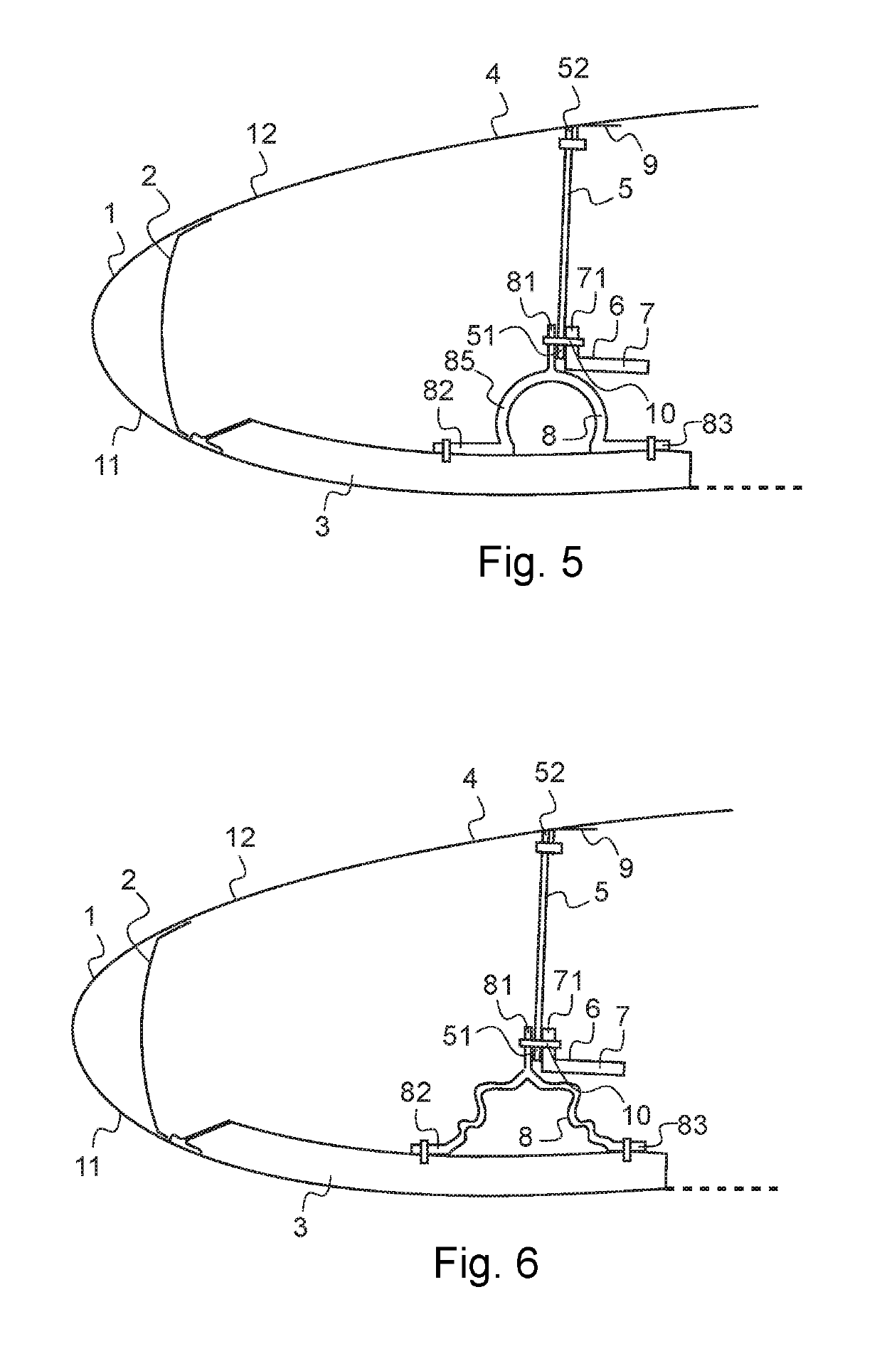
[0052]Referring to FIG. 3, the anterior part of a nacelle of an aircraft propulsion unit according to an exemplary embodiment is illustrated. FIG. 3 is a view in cross section which is partial, inasmuch as the anterior part is a structure substantially exhibiting symmetry of revolution about the longitudinal axis “A” of the propulsion unit it is intended to equip. FIG. 3 depicts only a cross section of this substantially axisymmetric structure.

[0053]The configuration shown corresponds in particular to an anterior part of a nacelle for a UHBR engine. A UHBR engine has a bypass ratio (the mass ratio between the secondary flow and the primary flow) greater than or equal to fifteen. Such an engine has a large nacelle with a larg...


PUM


Abstract

An anterior part of a nacelle of an aircraft propulsion unit having an air inlet lip at the front end, an internal structure and an external panel extending the air inlet lip, and an annular rigidifying frame having an external peripheral edge connected to the external panel is disclosed. The anterior part of the nacelle includes a shock-absorbing element connected rigidly on the one hand to an internal peripheral edge of the rigidifying frame and on the other hand to the internal structure.

Description

CROSS REFERENCE TO RELATED APPLICATION[0001]This application claims priority to and incorporates by reference French Patent Application Number 1762722, filed Dec. 21, 2017.BACKGROUND1. Field of the Invention[0002]The present invention relates to aircraft propulsion units and, more particularly, to the nacelles of aircraft propulsion units.2. Description of the Related Art[0003]A propulsion unit is a device that generates thrust propelling forward the aircraft equipped with the propulsion unit.[0004]An aircraft propulsion unit is depicted by way of example in FIG. 1.[0005]The nacelle conventionally comprises an anterior part P1 forming an air inlet, and a main part P2.[0006]The anterior part P1 has the role of collecting air so as to ensure even flow towards the fan.[0007]The propulsion unit extends along a longitudinal axis “A”, and is symmetrically configured around the axis.[0008]A conventional structure of an anterior part of a nacelle of an aircraft propulsion unit, as known fro...

Claims


Application Information

Patent Timeline
IPC IPC(8): F01D21/04B64D29/00B64D33/02
CPCF01D21/045B64D29/00B64D33/02F02C7/04B64D2033/022B64D2033/0286
Inventor VINCHES, FREDERICALBET, GREGORYSENTIER, JULIEN
Owner AIRBUS OPERATIONS SAS
Why Eureka
Eureka Blog
Learn More