Discharge device for inductive devices

Active Publication Date: 2005-05-05
EDWARD C LEVY
View PDF18 Cites 16 Cited by
  • Summary
  • Abstract
  • Description
  • Claims
  • Application Information

AI Technical Summary

Benefits of technology

[0010] A resistance in the form of one or more resistors is connected in se

Problems solved by technology

The industrial applications in which these inductive devices are incorporated are such that the device and any controller are subject to harsh conditions in which damage to the equipment can easily result.
If the device is energized when it is abruptly disconnected from its power supply, a voltage le

Method used


Image

  • Discharge device for inductive devices
  • Discharge device for inductive devices
  • Discharge device for inductive devices

Examples


Embodiment Construction

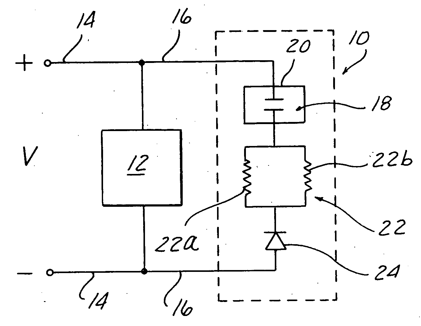
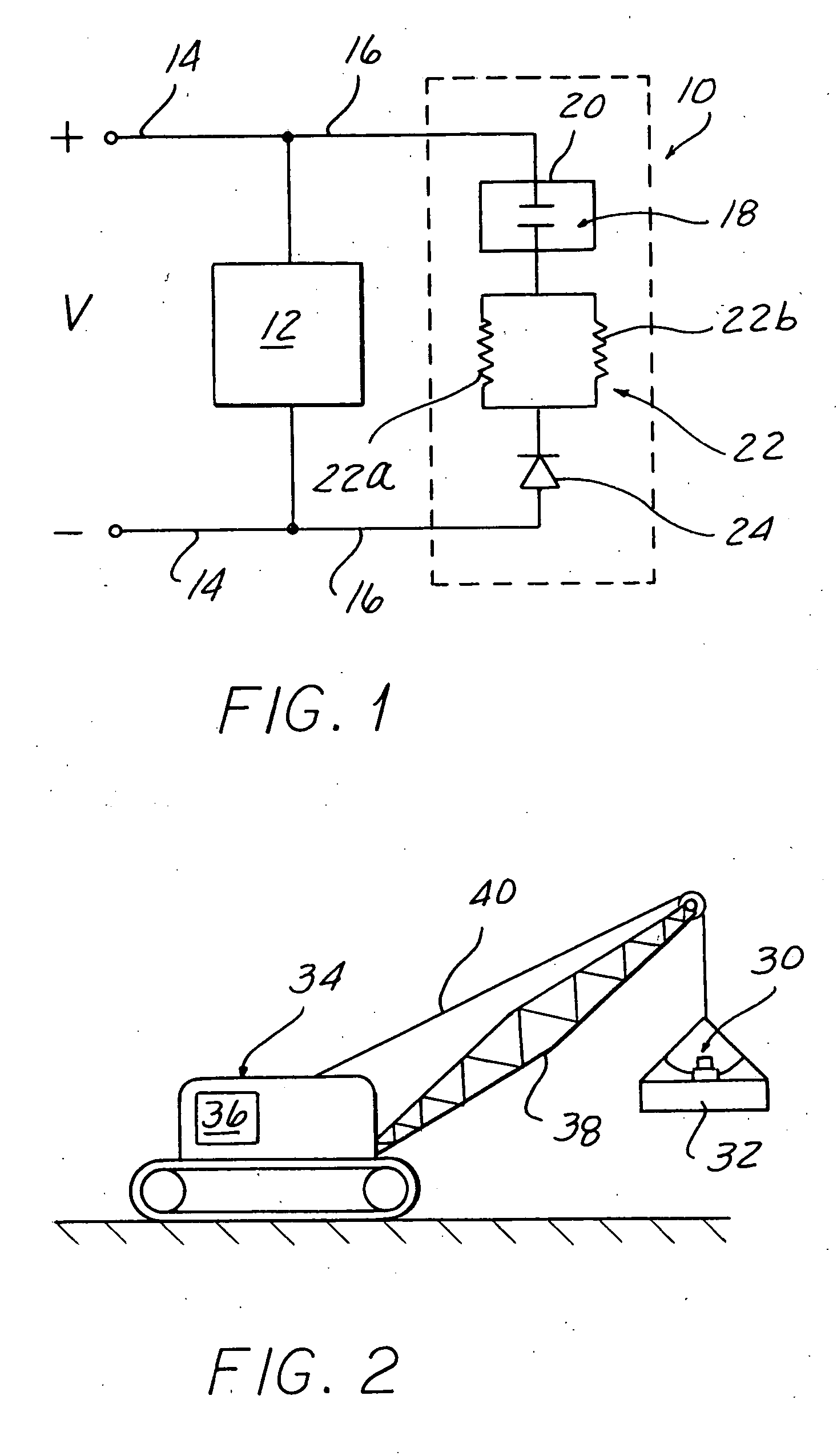
[0019] An apparatus and method for protecting an inductive device, such as an electromagnet, from excessively high voltages resulting from an open circuit is described with reference to FIGS. 1-6. An open circuit of the inductive device as used herein refers to any circumstance under which the inductive device, when energized by a power source, is abruptly cut off from that source. FIG. 1 is a simplified electrical schematic of one embodiment of the discharge device 10. The inductive device 12 is connected by conductors 14 to a variable or fixed DC supply voltage V with the indicated polarity. The discharge device 10 is connected by conductors 16 such that the discharge device 10 is in parallel with the inductive device 12. Thus, the discharge device 10 is in parallel with both the inductive device 12 and the variable DC supply voltage V. The discharge device 10 includes a spark gap 18 sealed in a spark chamber 20 filled with an inert gas. The spark gap 18 comprises two spaced elect...


PUM


Abstract

A method and apparatus for protecting an energized inductive device such as an electromagnet from an open circuit, i.e., the loss of the power source for the inductive device. A diode is connected across terminals of the inductive device such that when the inductive device is normally energized, the diode is reversed-biased. A spark gap enclosed in a housing is connected in series with the diode. An inert gas fills the housing. A resistance in the form of one or more resistors is in series with both the diode and the spark gap. Upon the sudden loss of supply to the energized device, the diode, the resistance and the spark gap form a path for the discharge of energy from the inductive device.

Description

BACKGROUND OF THE INVENTION [0001] 1. Field of the Invention [0002] The invention relates to controls for inductive devices and, more particularly, to a discharge device for a large inductive device such as an electromagnet. [0003] 2. Description of the Related Art [0004] Large inductive devices are oftentimes incorporated into industrial applications. For example, an electromagnet is merely an encased inductor. Electromagnets can be used with a crane as lifting magnets in the steel industry for scrap material handling. The electromagnet is coupled to a magnet controller, which includes an electrical circuit that typically receives a DC voltage from a generator or other source and controls the voltage applied to, and thus the current flow through, the electromagnet. [0005] The industrial applications in which these inductive devices are incorporated are such that the device and any controller are subject to harsh conditions in which damage to the equipment can easily result. For exa...

Claims


Application Information

Patent Timeline
IPC IPC(8): H01T1/00H02H9/04
CPCH01T1/00
Inventor POLLOCK, MICHAELKAHL, FRED
Owner EDWARD C LEVY
Why Eureka
Try Eureka