Gas turbine stage

Active Publication Date: 2015-01-15
MTU AERO ENGINES GMBH
View PDF10 Cites 2 Cited by
  • Summary
  • Abstract
  • Description
  • Claims
  • Application Information

AI Technical Summary

Benefits of technology

The patent describes a technical solution for reducing the gap between the rotating and stationary parts of a gas turbine engine. This is achieved by reinforcing the leading edge of the stator vane with a surface treatment or increased material thickness. This can improve the performance of the engine in the event of a shaft breakage.

Problems solved by technology

If, in the event of a shaft breakage, the compressor load is abruptly removed, the gas turbine stage(s) may overspeed, which is not desired.

Method used


Image

  • Gas turbine stage
  • Gas turbine stage
  • Gas turbine stage

Examples


Embodiment Construction

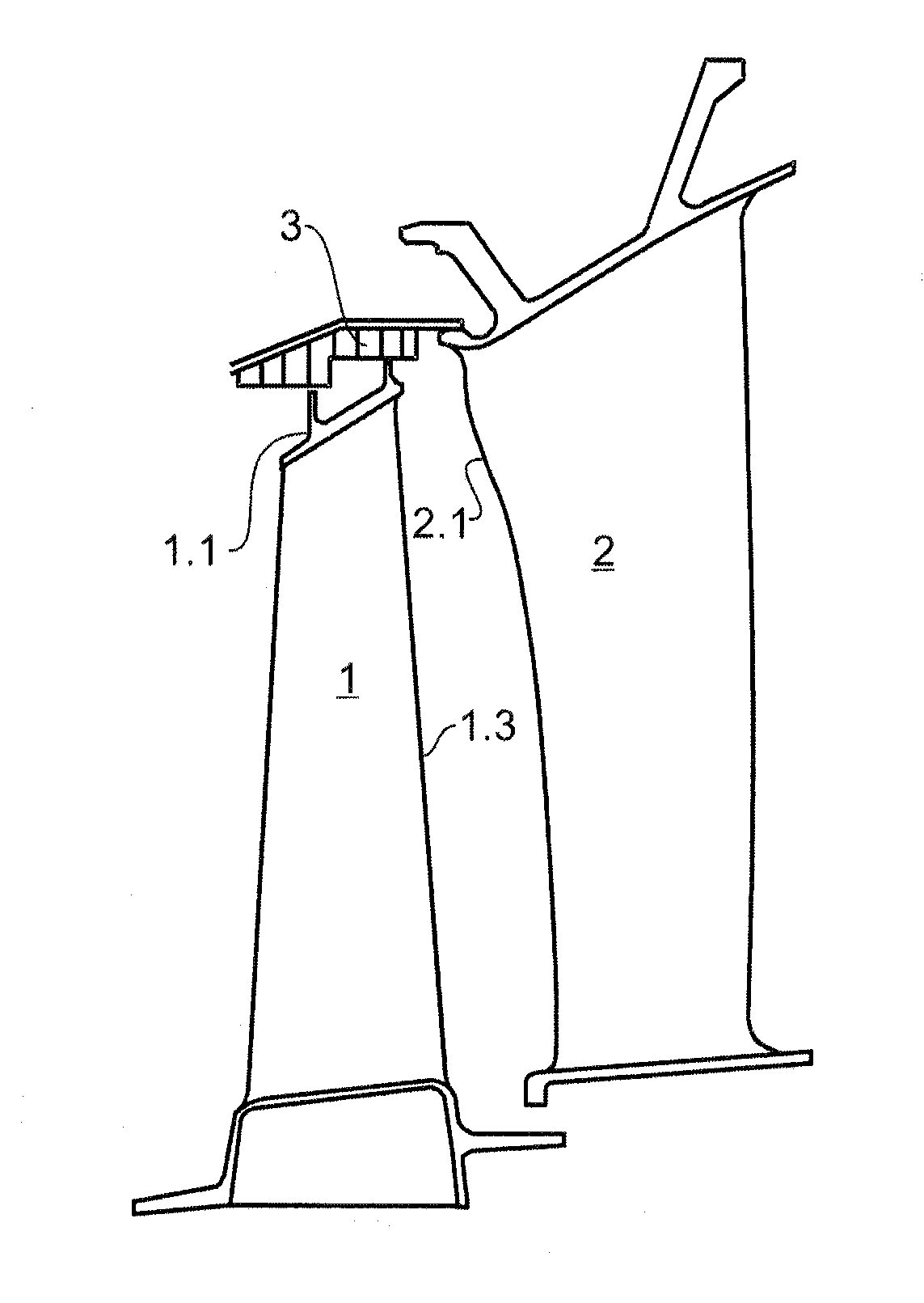
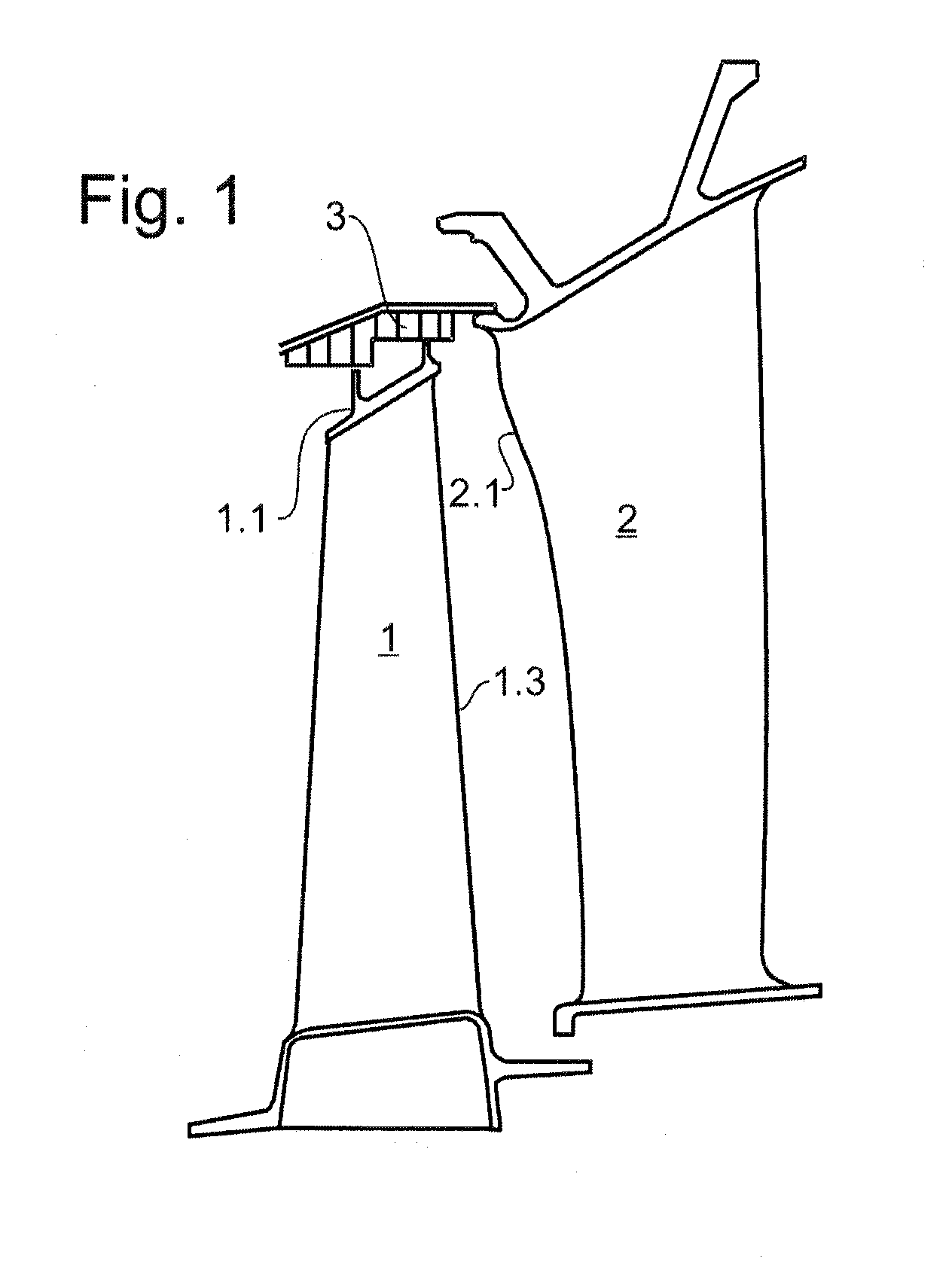
[0037]FIG. 1 shows a portion of a gas turbine stage of low-pressure turbine of an aircraft engine according to an embodiment of the present invention. The gas turbine stage is an intermediate turbine stage, but may also be a forwardmost or rearwardmost turbine stage.

[0038]The gas turbine stage includes a rotor blade array having a plurality of circumferentially distributed rotor blades which are detachably or permanently connected to a rotor. At their radially outer ends, the rotor blades have an outer shroud 1.1 having two sealing fins facing an outer honeycomb seal 3.

[0039]The gas turbine stage includes, adjacent to and downstream of the rotor blade array (to the right in FIG. 1), a stator vane array having a plurality of circumferentially distributed stator vanes 2 which have leading edges 2.1 facing the rotor blade array.

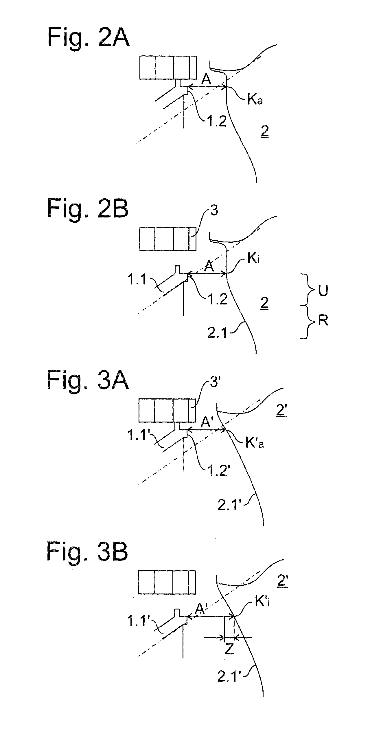
[0040]FIG. 2A shows an enlarged detail of FIG. 1, in which a downstream rear face 1.2 of the outer shroud 1.1 of the rotor blade array of the gas turbine stage ...


PUM


Abstract

A gas turbine stage including a rotor blade array having a plurality of rotor blades and an adjacent stator vane array having a plurality of stator vanes which have leading edges facing the rotor blade array. In a first radial position of a rear face of the rotor blade array, a minimum axial gap is formed between this rear face and an opposite first contact region a stator vane leading edges, and in a second radial position of the rear face different from the first position, the minimum axial gap is formed between the rear face and an opposite second contact region. Between the first and second contact regions, this stator vane leading edge has an axial offset of no more than 0.6% of a radial height of the stator vane leading edge.

Description

[0001]This claims the benefit of German Patent Application DE 13 176 420.1, filed Jul. 12, 2013 and hereby incorporated by reference herein.[0002]The present invention relates to a gas turbine stage including a rotor blade array having a plurality of rotor blades and an adjacent stator vane array having a plurality of stator vanes, and to a gas turbine, in particular an aircraft engine, having such a gas turbine stage.BACKGROUND[0003]In a gas turbine, such as is known, for example, from U.S. Pat. No. 6,312,219 B1, one or more gas turbine stages drive one or more compressor stages and / or fans via one or more shafts. In one or more of the gas turbine stages, a stator vane array is provided downstream of a rotor blade array to vary the velocity of the gas flow.[0004]If, in the event of a shaft breakage, the compressor load is abruptly removed, the gas turbine stage(s) may overspeed, which is not desired. Such overspeeding can be reduced or prevented in that the fast rotating rotor blad...

Claims


Application Information

Patent Timeline
IPC IPC(8): F01D9/04F01D21/04
CPCF01D9/041F01D21/045F01D5/141F05D2240/121Y02T50/60
Inventor MAHLE, INGAHUEBNER, NORBERTSTANKA, RUDOLFSCHUETZ, GOTTFRIEDCLEESATTEL, NORMAN
Owner MTU AERO ENGINES GMBH
Why Eureka
Try Eureka