In-wheel motor with brake

Active Publication Date: 2014-06-12
E TRACTION EURO BV
View PDF12 Cites 26 Cited by
  • Summary
  • Abstract
  • Description
  • Claims
  • Application Information

AI Technical Summary

Benefits of technology

[0034]In an embodiment said housing comprises a through passage for a wire or rod connected to the brake system from outside said wheel, wherein a displacement of the wire or rod relative to the brake system actuates the brake system. The present invention thus provides a mechanical brake system inside the wheel, which brake system may easily be connected to one or more brake wires or the like of a vehicle to which the wheel is attached. Preferably displacement of the wire or rod puts the brake system in a parking mode.
[0035]In an embodiment the housing comprises a through passage for a duct or conduit comprising brake fluid connected to the brake system from outside said wheel, wherein a pressure change of said brake fluid in the duct or conduct actuates the brake system. The wheel may thus easily be connected to o

Problems solved by technology

However, in the known assembly, the rotating motor portion is arranged within the non-rotating motor portion, and a

Method used


Image

  • In-wheel motor with brake
  • In-wheel motor with brake
  • In-wheel motor with brake

Examples


Embodiment Construction

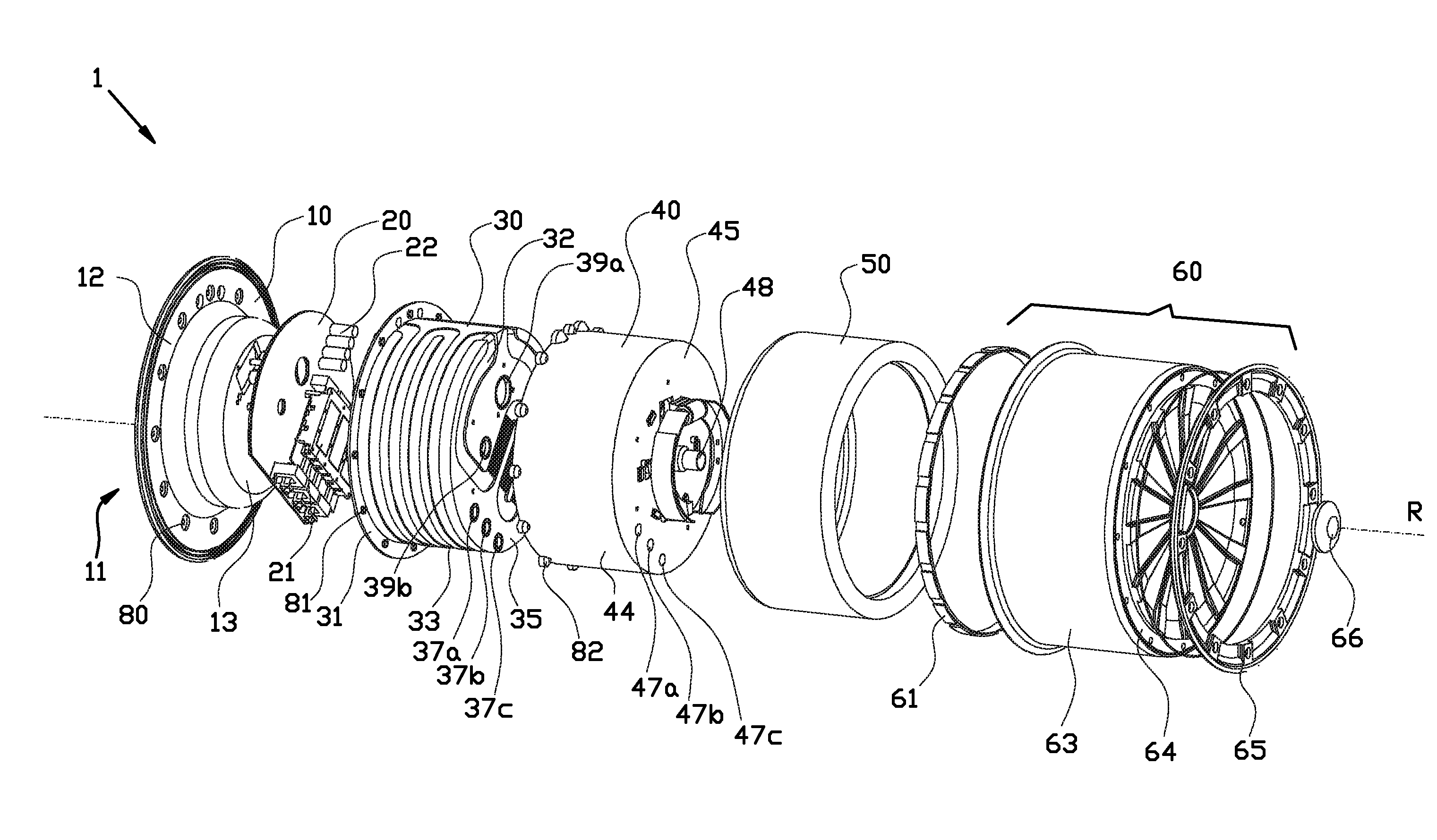
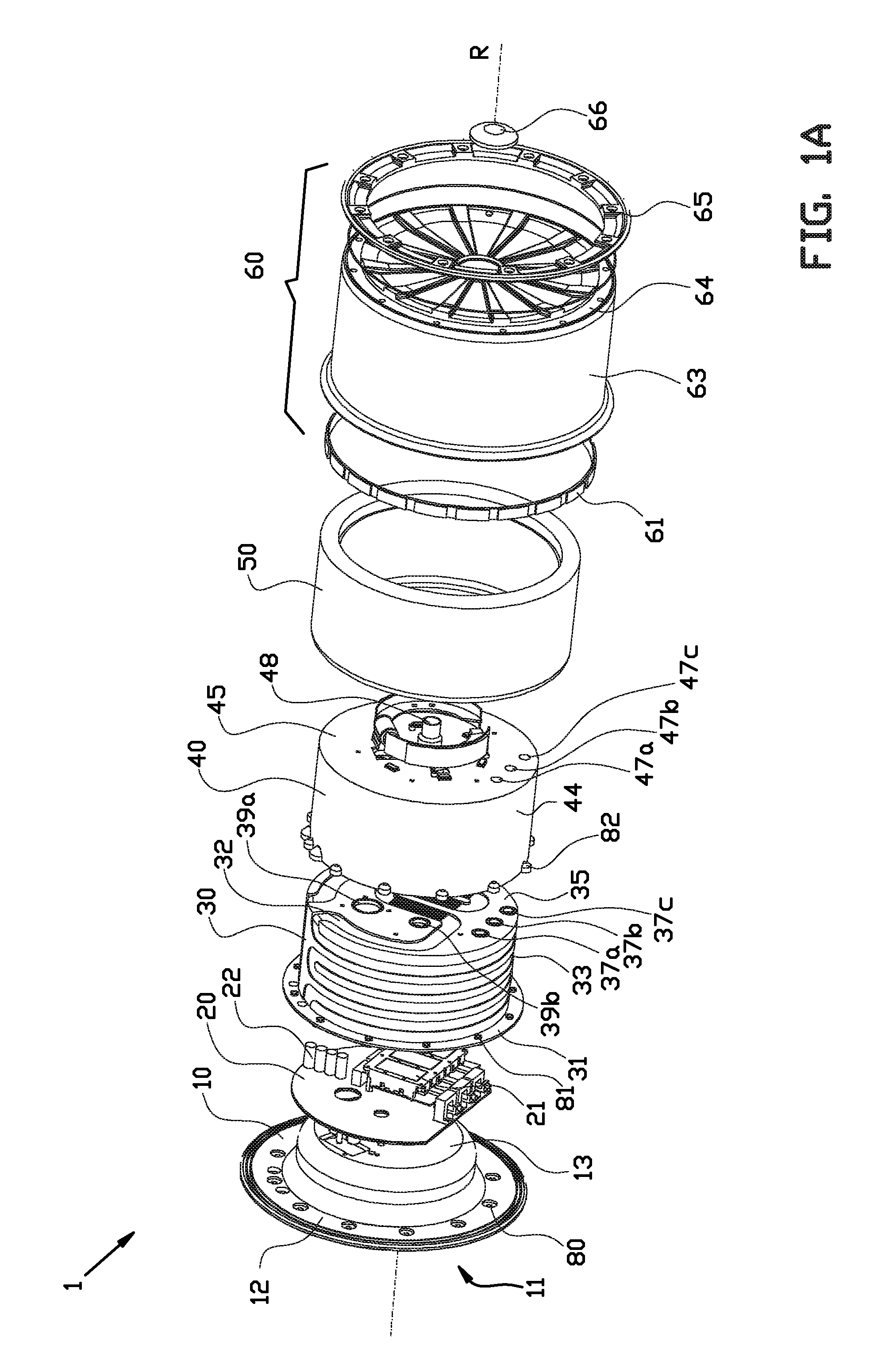
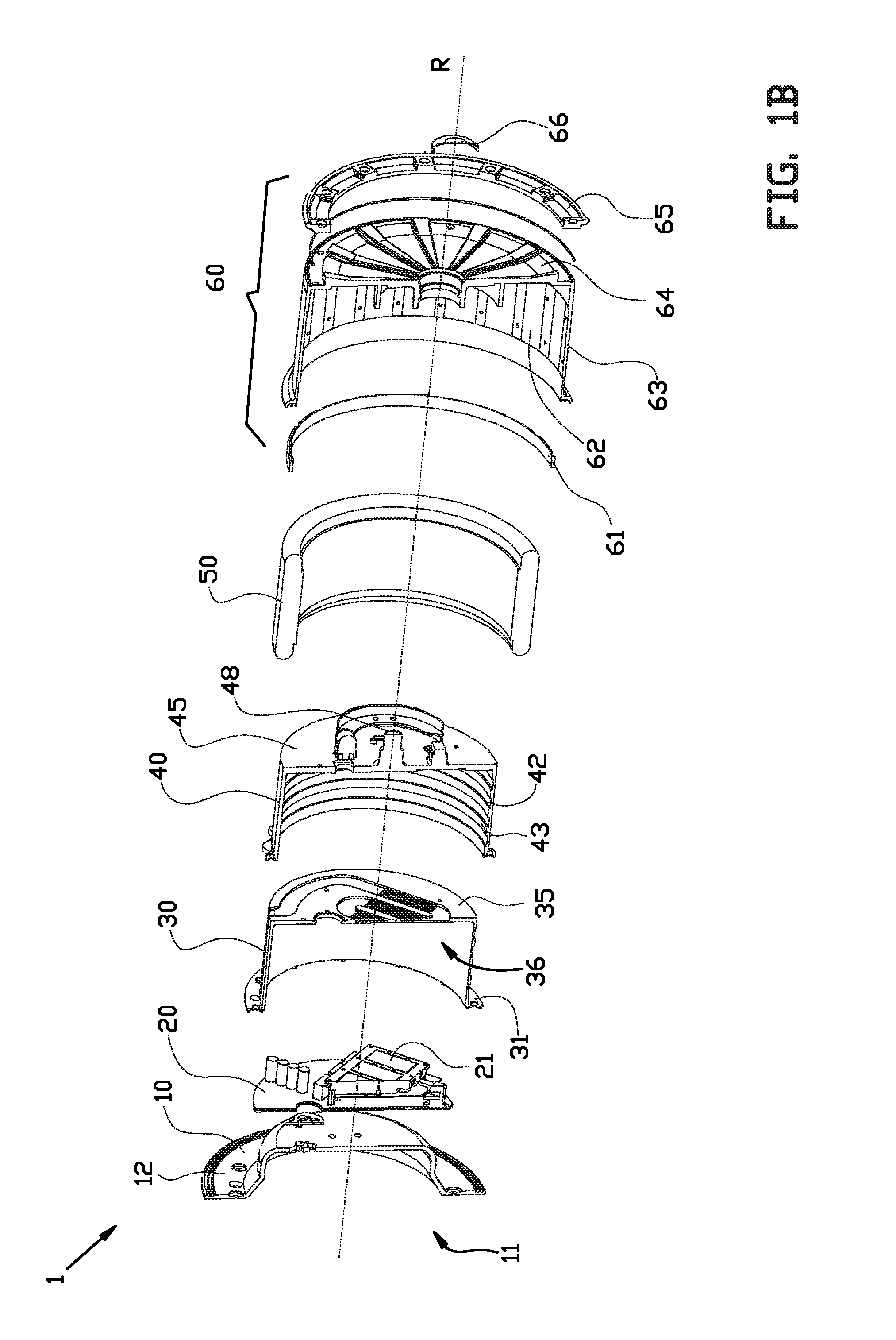
[0066]FIGS. 1A and 1B show an exploded view of a wheel 1 according to the invention and a cross-sectional view thereof respectively. The wheel 1 comprises an attachment adapter, or adapter plate 10, and a hollow body 40, which when assembled together with cooling system 30 forms a housing. The adapter plate 10 comprises a flange 12 at a first side 11 of the housing for mounting the wheel to a vehicle. Alternatively, the adapter plate 10 may be omitted and the housing 30,40 may be mounted with a first side 31 directly to the vehicle. The wheel 1 comprises an electrical motor comprising a stator 50, which is rotation-fixedly connected to the housing 30,40, and a rotor 60, which is rotationally coupled to said stator and which has an axis of rotation R. The stator 50 comprises a number of stator windings of a conductive material, which form one or more electromagnets as known in the art. The rotor 60 comprises permanent magnets 62 (see FIG. 1B) arranged around the axis of rotation R an...


PUM

PropertyMeasurementUnit
Distanceaaaaaaaaaa
Pressureaaaaaaaaaa
Poweraaaaaaaaaa

Abstract

The invention relates to wheel for a vehicle comprising, inside the wheel:
    • a housing having a first side for mounting to a vehicle,
    • an electrical motor for driving movement of said vehicle, said electrical motor comprising a stator rotation-fixedly connected to said housing and a rotor rotationally coupled to said stator and having an axis of rotation, said stator being arranged within said rotor, and
    • a brake drum, forming an integral piece of equipment with the rotor.
The invention further relates to a vehicle provided with such a wheel and a method and an adapter plate for mounting such a wheel to a vehicle, and to such a wheel having a rim system in which the rim forms an integral part with said rotor and with a brake drum of the brake system, i.e. forming one integral price of equipment.

Description

CROSS REFERENCE[0001]This application is a continuation of PCT / NL2012 / 050559 filed Aug. 10, 2012, which claims priority to The Netherlands application number 2007261 filed Aug. 12, 2011 and U.S. provisional application No. 61 / 523,145 filed Aug. 12, 2011, the entire contents of each of which are incorporated herein in their entireties.BACKGROUND[0002]The invention relates to an in-wheel motor with a brake. Such an in-wheel motor is described for instance in International Patent application WO 2010 / 101914, describing a wheel assembly for a vehicle, comprising: a non-rotating support member, a wheel including a rim, a spider and a wheel hub, the rim having a radially inner surface, wherein the wheel is rotatably supported by the non-rotating support member for rotation about a wheel axis; and an electric motor having an axially extending motor aperture, wherein the electric motor includes a non-rotating motor portion and a rotating motor portion, wherein the rotating motor portion is o...

Claims


Application Information

Patent Timeline
IPC IPC(8): B60K7/00F16D65/78
CPCB60L3/003B60L3/0061B60L3/0076B60L7/006B60L7/14B60L7/24B60L15/20B60L15/2009B60L2220/44B60L2240/36B60L2240/423Y02T10/72B60L50/51Y10T29/49826B60K7/0007Y02T10/64Y02T10/70F16D65/78
Inventor HEINEN, ADRIANUS JOHANNESVAN SEVENTER, TIMOTHY
Owner E TRACTION EURO BV
Why Eureka
Try Eureka