Device and method for assisting laparoscopic surgery - rule based approach

a technology of laparoscopic surgery and equipment, applied in the direction of instruments, catheters, applications, etc., can solve the problems of not being available in all hospitals, difficult for the operating medical assistant to hold the endoscope steady, and inability to address another complicating interface aspect of laparoscopic surgery

Active Publication Date: 2014-06-12
TRANSENTERIX EURO SARL
View PDF6 Cites 128 Cited by
  • Summary
  • Abstract
  • Description
  • Claims
  • Application Information

AI Technical Summary

Benefits of technology

[0227]It is another object of the present invention to provide the surgical controlling system as defined above, further comprising a maneuvering subsystem communicable with the controller, the maneuvering subsystem is adapted to spatially reposition at least one surgical tool during a surgery according to the predetermined set of rules, such that if said movement of said at least one surgical tool is a RESTRICTED movement, said maneuvering subsystem prevents said movement.

Problems solved by technology

The main problem is that it is difficult for the operating medical assistant to hold the endoscope steady, keeping the scene upright.
The equipment is often expensive and is not available in all hospitals.
The above interfaces share the following drawbacks:a. A single directional interface that provide limited feedback to the surgeon.b. A cumbersome serial operation for starting and stopping movement directions that requires the surgeon's constant attention, preventing the surgeon from keeping the flow of the surgical procedure.
However, these improved technologies still fail to address another complicating interface aspect of laparoscopic surgery, in that they do not allow the surgeon to signal, to automated assistants or to human assistants or to surgical colleagues, which instrument his attention is focused on.

Method used


Image

  • Device and method for assisting laparoscopic surgery - rule based approach
  • Device and method for assisting laparoscopic surgery - rule based approach
  • Device and method for assisting laparoscopic surgery - rule based approach

Examples


example 1

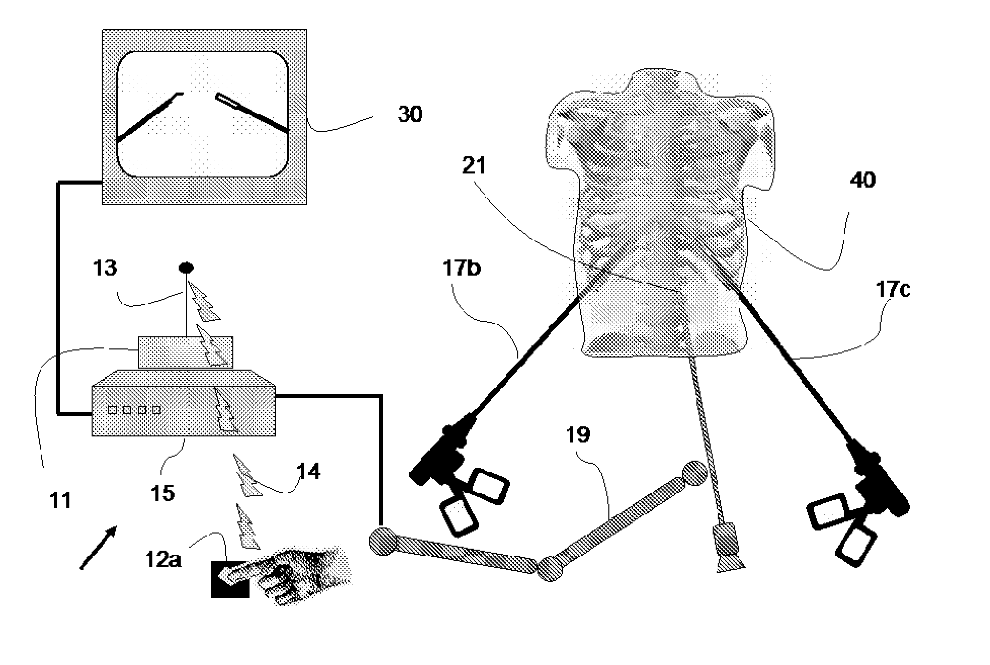
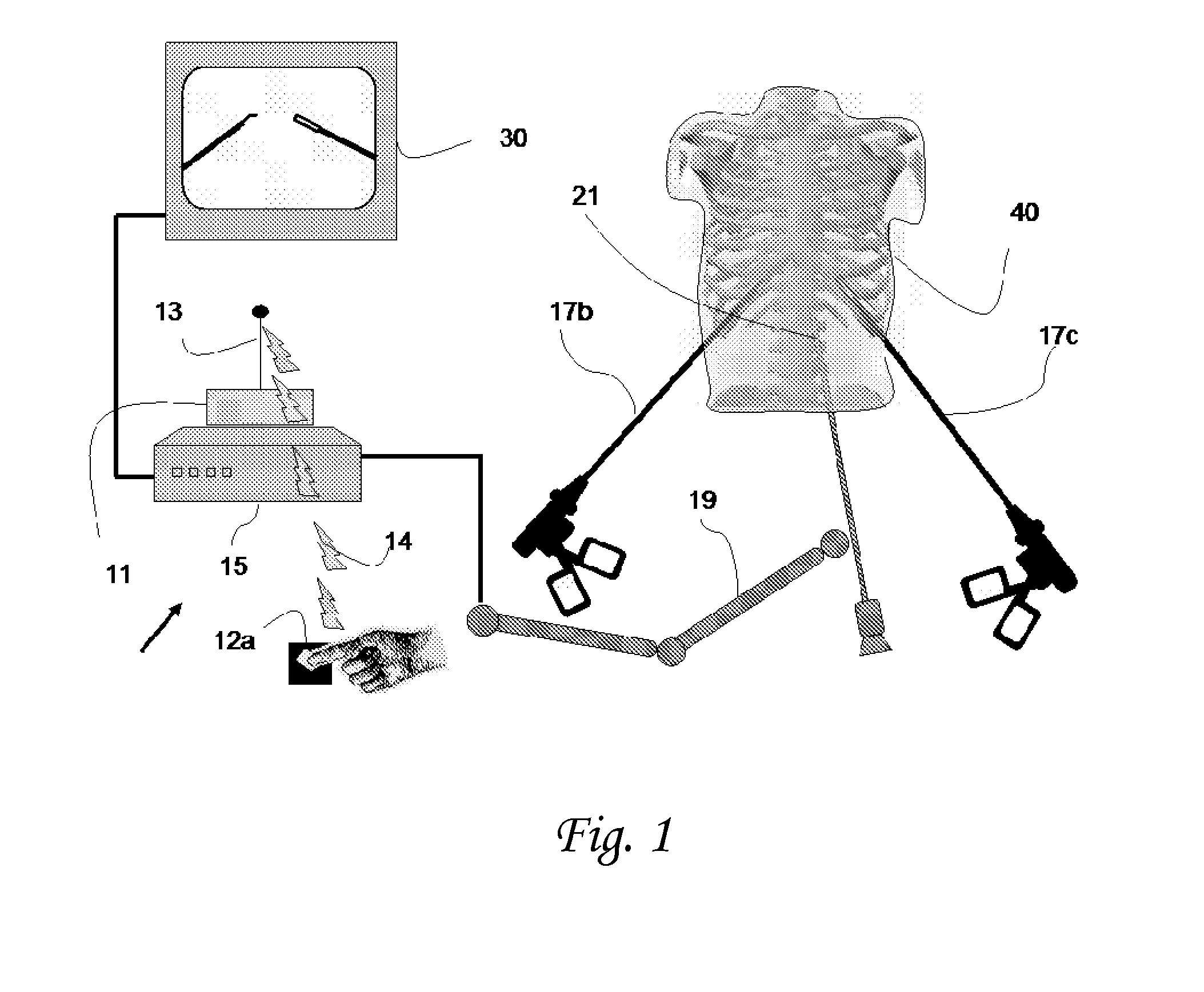
Tracking System with Collision Avoidance System

[0559]One embodiment of such a rule-based system will comprise the following set of commands:

Detection (denoted by Gd):

Gd1 Tool location detection function

Gd2 Organ (e.g. Liver) detection function

Gd3 Movement (vector) calculation and estimation function

Gd4 Collision probability detection function

Tool Instructions (denoted Gt):

Gt1 Move according to manual command

Gt2 Stop movement

[0560]The scenario—manual move command by the surgeon: Locations Gd1(t) and Gd2(t) are calculated in real time at each time step (from an image or location marker).

[0561]Tool movement vector Gd3(t) is calculated from Gd1(t) as the difference between the current location and at least one previous location (probably also taking into account previous movement vectors).

[0562]The probability of collision—Gd4(t)—is calculated, for example, from the difference between location Gd1 and location Gd2 (the smaller the distance, the closer the proximity and the higher the pr...

example 2

Tracking System with Soft Control—Fast Movement when Nothing is Nearby, Slow Movement when Something is Close

[0569]One embodiment of such rule-based system comprises the following set of commands:

Detection (denoted by Gd):

Main Tool location detection function (denoted by GdM);

Gd-tool1-K—Tool location detection function;

Gd-organ2-L—Organ (e.g. Liver) detection function;

Gd3 Main Tool Movement (vector) calculation and estimation function;

Gd4 Proximity probability detection function;

Tool Instructions (denoted Gt):

Gt1 Movement vector (direction and speed) according to manual command

[0570]The scenario—manual move command by the surgeon:

[0571]Locations GdM(t), Gd-tool1-K(t) and Gd-organ2-L(t) are calculated in real time at each time step (from image or location marker).

[0572]Main Tool Movement Vector Gd3(t) is calculated per GdM (t) as the difference between the current location and at least one previous location (probably also taking into account previous movement vectors)

[0573]The proxim...

example 3

Tracking System with No-Fly Rule / Function

[0575]In reference to FIG. 4, which shows, in a non-limiting manner, an embodiment of a tracking system with no-fly rule. The system tracks a tool 310 with respect to a no-fly zone (460), in order to determine whether the tool will enter the no-fly zone (460) within the next time step. In this example, the no-fly zone 460 surrounds the liver.

[0576]FIGS. 4a and 4b show how the behavior of the system depends on the location of the tool tip with respect to the no-fly zone, while FIGS. 4c and 4d show how movement of the tool affects the behavior.

[0577]In FIG. 4a, the tool 310 is outside the no-fly zone rule / function 460 and no movement of the tool is commanded. In FIG. 4b, the tool 310 is inside the no-fly zone 460.

[0578]The no-fly zone rule / function performs as follows:

[0579]In the embodiment illustrated, a movement 350 is commanded to move the tool 310 away from the no-fly zone 460. In other embodiments, the system prevents movement further int...


PUM


Abstract

The present invention provides a surgical tracking system for assisting an operator to perform a laparoscopic surgery of a human body, said surgical tracking system comprising: a. at least one endoscope adapted to acquire real-time images of a surgical environment within said human body; b. a maneuvering subsystem adapted to control the spatial position of said endoscope during said laparoscopic surgery; and, c. a tracking subsystem in communication with said maneuvering subsystem, adapted to control the maneuvering system so as to direct and modify the spatial position of said endoscope to a region of interest.

Description

FIELD OF THE INVENTION[0001]The present invention generally relates to means and methods for improving the interface between the surgeon and the operating medical assistant or between the surgeon and an endoscope system for laparoscopic surgery. Moreover, the present invention discloses a device useful for spatially repositioning an endoscope to a specific region in the human body during surgery.BACKGROUND OF THE INVENTION[0002]In laparoscopic surgery, the surgeon performs the operation through small holes using long instruments and observing the internal anatomy with an endoscope camera. The endoscope is conventionally held by a human camera assistant (i.e. operating medical assistant) since the surgeon must perform the operation using both hands. The surgeon's performance is largely dependent on the camera position relative to the instruments and on a stable image shown by the monitor. The main problem is that it is difficult for the operating medical assistant to hold the endosco...

Claims


Application Information

Patent Timeline
Patent Type & Authority Applications(United States)
IPC IPC(8): A61B19/00A61B1/313A61B1/04A61B5/06A61B1/06A61B6/03A61B8/12A61B8/08A61B1/00A61B17/00
CPCA61B1/3132A61B1/00009A61B5/064A61B1/00149A61B1/0016A61B90/10A61B34/20A61B2034/301A61B34/25A61B34/30A61B2090/0811A61B2034/107A61B2034/2051A61B2034/2065A61B90/39A61B1/00006G16H20/40G16H30/40A61B1/00042A61B1/04A61B1/00011A61B1/0002A61B1/00045A61B1/0661A61B5/062A61B6/032A61B8/0841A61B8/12A61B17/00234
Inventor SHOLEV, MORDEHAIPFEFFER, UDIFRIMER, MOTTI
Owner TRANSENTERIX EURO SARL
Why Eureka
Try Eureka