Swinging leg pendulum movement aid for walking, and assistance force control method

a technology of pendulum movement and movement aid, which is applied in the direction of walking aids, physical therapy, chiropractic devices, etc., can solve the problems of reducing the ability and reducing the ability of users to walk. , to achieve the effect of reducing the ability of walking, reducing the difficulty of walking, and effectively inhibiting the decrease of muscle strength

Active Publication Date: 2014-06-12
KYUSHU UNIV +1
View PDF12 Cites 29 Cited by
  • Summary
  • Abstract
  • Description
  • Claims
  • Application Information

AI Technical Summary

Benefits of technology

[0032]With the control method of this mode, by applying assistance force to the pendulum movement of the swinging leg during walking and aiding the realizing of the original two legged walking posture, the walking movement is supported with a small force, walking movement is promoted using the decreased walking ability person's own movement and muscle strength, and thus it is possible to effectively inhibit a decrease in muscle strength. With this mode, the assistance force applied to the swinging leg can be applied in advance to that leg from before that leg floats up from the ground, or can be applied after

Problems solved by technology

Because of that, there was the problem that it was difficult to avoid the device from becoming larger or heavier because a large output was required.
In fact, with the conventional assistive devices that aid the muscle strength with a large output assistance for the grounding side leg muscle strength, as a result of being able to do this with little burden on the muscle strength of the user himself, there was the problem that it was difficult to expect an effect of developing the user's own muscle strength and suppressing a decrease in muscle strength.
Because of that, particularly with a person with decreased walking ability referred to as locomotive syndrome or the like for which there is a walking disability for a reason such as aging or the like, but does not go so far as being unable to walk, even when using an assistive device which performs muscle strength assistance to the grounding leg using a co

Method used


Image

  • Swinging leg pendulum movement aid for walking, and assistance force control method
  • Swinging leg pendulum movement aid for walking, and assistance force control method
  • Swinging leg pendulum movement aid for walking, and assistance force control method

Examples


Embodiment Construction

[0052]Following, we will describe embodiments of the present invention while referring to the drawings.

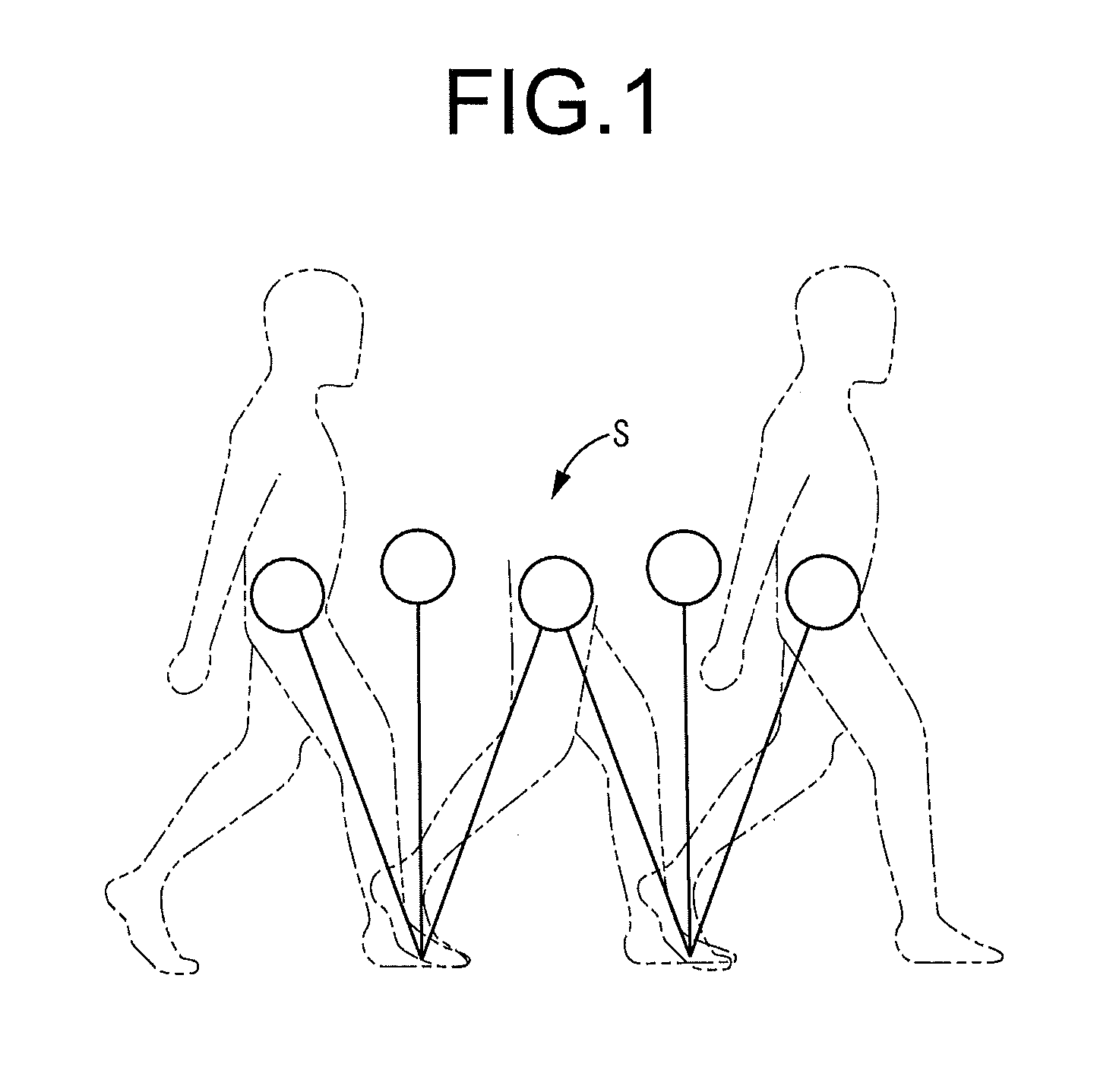
[0053]To start, the human walking mechanism is expressed by the inverted pendulum model S shown in FIG. 1. This inverted pendulum model S puts walking into model form using the displacement of the pendulum state of the gravity center with the grounding point as the fulcrum point, and the equation of motion is given by Expression 1.

Iθ″=mgLθω=gL[Expression1]

L: Distance between the center of gravity and the ankle joint

g: Gravitational acceleration

θ: Angle formed by distance L and the vertical direction

I: Inertia moment

m: Mass of the center of gravity

[0054]Also, from Expression 1 noted above, the relationship between the center of gravity position (Lθ) and velocity (Iθ′) is given by Expression 2 as an energy conservation law.

12(Iθ′)2-12ω2(Lθ)2=Em[Expression2]

E / m: Mechanical energy per unit of mass [J / kg]

[0055]Here, to continue walking with the center of gravity continuing to move forwa...


PUM


Abstract

A swinging leg pendulum movement aid for walking including a pair of assisting units for a left leg and a right leg each having a drive source for applying a pulling force to an auxiliary force transmission part, a joint angle sensor for detecting a joint angle of user's hip joints, and a control member for driving the drive sources of the respective assisting units corresponding to changes in the joint angle and applying an assistance force in a forward swinging direction to the swinging leg that kicked off a ground so as to aid a pendulum movement of the swinging leg.

Description

INCORPORATED BY REFERENCE[0001]The disclosure of Japanese Patent Application No. 2012-162113 filed on Jul. 20, 2012 including the specification, drawings and abstract is incorporated herein by reference in its entirety. This is a Continuation of International Application No. PCT / JP2013 / 003371 filed on May 28, 2013.BACKGROUND OF THE INVENTION[0002]1. Field of the Invention[0003]The present invention relates to a swinging leg pendulum movement aid for walking and an assistance force control method. This invention is used by a person with decreased walking ability or the like, and promotes walking movement using his own muscle strength by supporting walking movement with a small force. For example, by increasing the walking speed, the invention is able to effectively suppress a decrease in muscle strength. Meanwhile, when keeping a fixed walking speed, for example, the invention is able to assist longer distance walking by walking being supported for a long period with a lower amount o...

Claims


Application Information

Patent Timeline
IPC IPC(8): A61H3/00
Inventor YAMAMOTO, MOTOJITAKASUGI, SHIN-ICHIROSATO, MASANORIKOMATSU, TAKAHIROHASHIMOTO, KAZUNOBU
Owner KYUSHU UNIV
Why Eureka
Try Eureka