Computer-Implemented System And Method For Analyzing Machined Part Manufacturability And Performing Process Planning

a machined part and process planning technology, applied in the field of computer-implemented system and process planning, can solve the problems of time-consuming and expensive iterations required to perform validation of human-generated manufacturing process plans, limited machining space, and inability to perform manufacturability analysis and automation of process plans

Active Publication Date: 2014-06-12
SANDVIK INTELLECTUAL PROPERTY AB
View PDF11 Cites 32 Cited by
  • Summary
  • Abstract
  • Description
  • Claims
  • Application Information

AI Technical Summary

Benefits of technology

[0009]A Web-based system and method uses a model of the manufacturing setup and knowledge of a designed part with arbitrary geometry to produce process plans in two successive stages. First, the part geometry is analyzed. A query of determining the maximal volume machinable from an oriented machining tool is transformed into determining the visibility of the part surface from the perspective of a hypothetical camera placed at the tip of the oriented machining tool. Second, a collection of the maximal machinable volumes over the set of all tool orientations is collected. Combinations of the maximal machinable volumes covering the entire difference between the raw stock and the desired part are evaluated for providing feedback on manufacturability and process plans. In a further embodiment, manufacturability is analyzed for tools and machines with arbitrary geometric complexity using high dimensional configuration space analysis.

Problems solved by technology

The iterations required to perform validation of human-generated manufacturing process plans can be time-consuming and expensive.
Manufacturability analysis and automation of process plans are complex problems that rely on advanced geometric reasoning at the part level and combining those results of that reasoning with a model of the manufacturing setup, particularly the tools used to machine each part, to aid both the design and manufacturing engineer.
In practice, however, machining is going to be limited by the available workspace, or the set of positions and orientations achievable by the tool.
For an infinitesimally thin tool, the heightmap value is exact, but for a finite thickness tool, collision is still an issue, which is why Pacc≠Pvis and Pinacc⊂Pvis.

Method used


Image

  • Computer-Implemented System And Method For Analyzing Machined Part Manufacturability And Performing Process Planning
  • Computer-Implemented System And Method For Analyzing Machined Part Manufacturability And Performing Process Planning
  • Computer-Implemented System And Method For Analyzing Machined Part Manufacturability And Performing Process Planning

Examples


Embodiment Construction

Prior Art Validation of Human-Generated Manufacturing Process Plans

[0024]Traditionally, design and manufacture within an organization are operated as closely-related, yet functionally separate spheres of activity. Product design generally occurs first, followed by product realization and manufacture. The design of a part is treated as a discrete output from a design department and the validation of human-generated process plans for manufacturing the part occurs between the conclusion of design and commencement of product manufacturing.

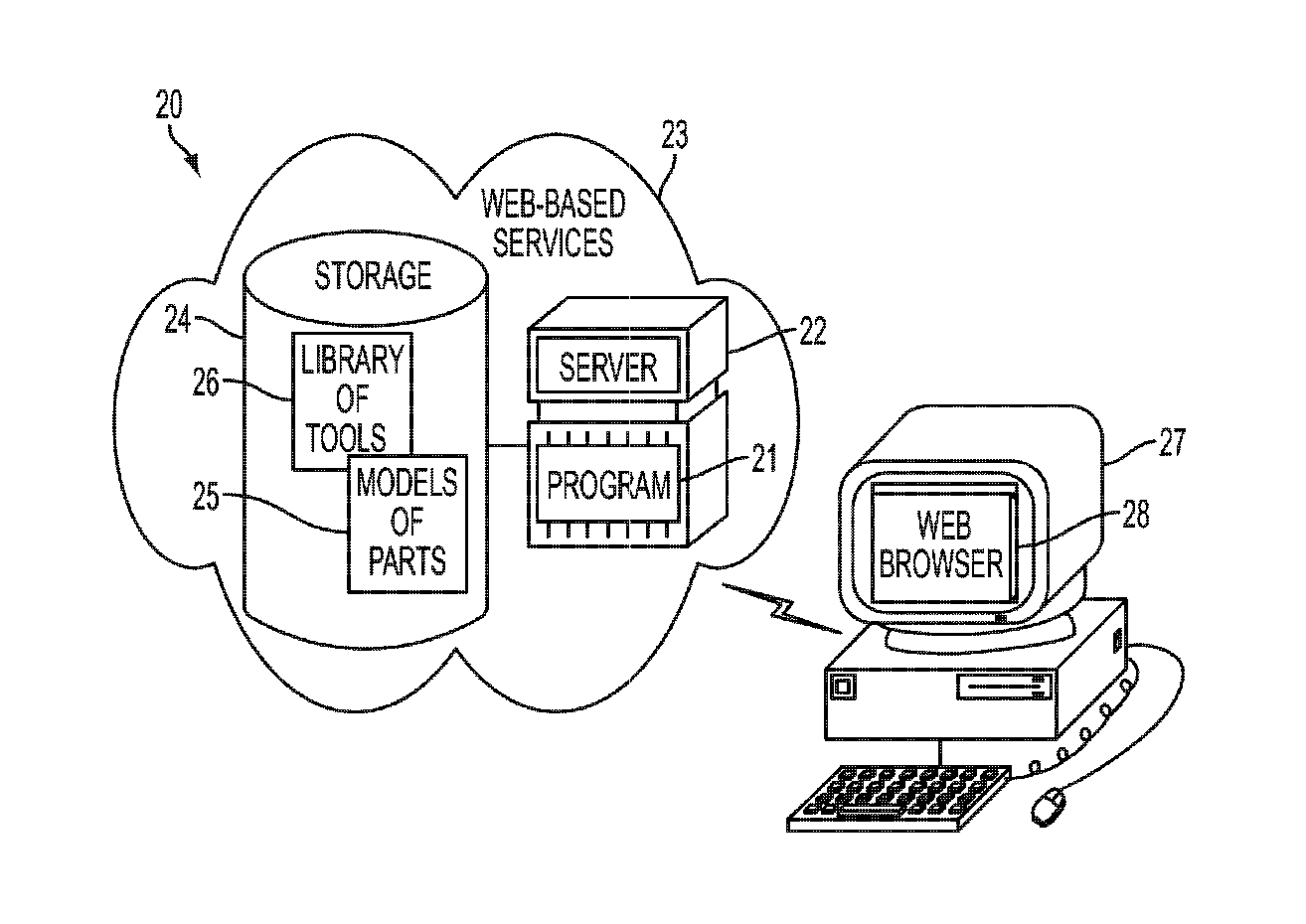
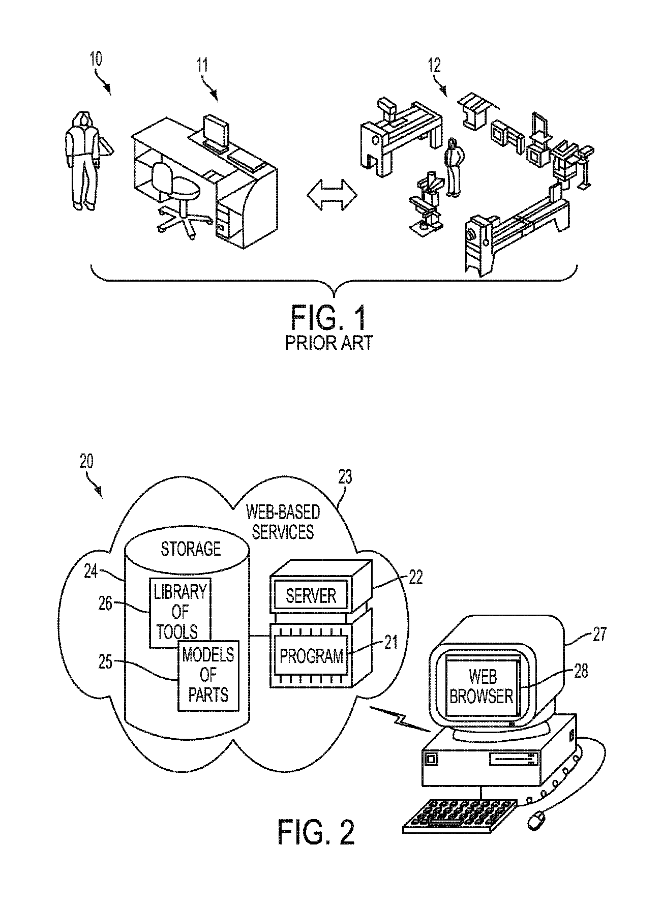
[0025]Conventional approaches to manufacturing process planning strive to better integrate product lifecycle management and physical shop floor production, while incidentally emphasizing the distinctions between design and manufacture. FIG. 1 is a functional block diagram showing, by way of example, a prior art system 10 for validation of human-generated manufacturing process plans. Manufacturability is evaluated during a subsequent stage in the produc...


PUM


Abstract

A Web-based system and method uses a model of the manufacturing setup and knowledge of a designed part with arbitrary geometry to produce process plans in two successive stages. First, the part geometry is analyzed. A query of determining the maximal volume machinable from an oriented machining tool is transformed into determining the visibility of the part surface from the perspective of a hypothetical camera placed at the tip of the oriented machining tool. Second, a collection of the maximal machinable volumes over the set of all tool orientations is collected. Combinations of the maximal machinable volumes covering the entire difference between the raw stock and the desired part are evaluated for providing feedback on manufacturability and process plans. In a further embodiment, manufacturability is analyzed for tools and machines with arbitrary geometric complexity using high dimensional configuration space analysis.

Description

FIELD[0001]This application relates in general to computer-aided process planning and, in particular, to a computer-implemented system and method for analyzing machined part manufacturability and performing process planning.BACKGROUND[0002]The machining of a part from raw stock or material, usually metal, is a form of subtractive manufacturing during which the raw material is progressively removed until the part reaches an intended shape and size. Operations during machining primarily involve turning, drilling and milling the raw material into the desired part, which respectively require removing the raw material by rotating the raw material against a stationary cutting tool, axially boring holes using a rotating bit with a cutting edge on a distal end whilst the raw material is held stationary, and cutting away the raw material using a rotating bit with cutting edges generally along the rotating bit's sides and distal end. Both drilling and milling involve traversing a rotating bit...

Claims


Application Information

Patent Timeline
Patent Type & Authority Applications(United States)
IPC IPC(8): G06F17/50
CPCG05B19/40938G05B19/4099G05B2219/35097G06T15/40G06T17/10G05B19/4069Y02P90/02G06F30/00
Inventor NELATURI, SAIGOPALBURTON, GREGORYKURTOGLU, TOLGAFRITZ, CHRISTIAN
Owner SANDVIK INTELLECTUAL PROPERTY AB
Why Eureka
Try Eureka