

Oil separator
- Summary
- Abstract
- Description
- Claims
- Application Information
AI Technical Summary
Benefits of technology
Problems solved by technology
Method used
Image

Examples
example
[0045]The following will specifically describe the invention for the first through third embodiments with reference to the drawings.
first embodiment
(1) Configuration of Oil Separator
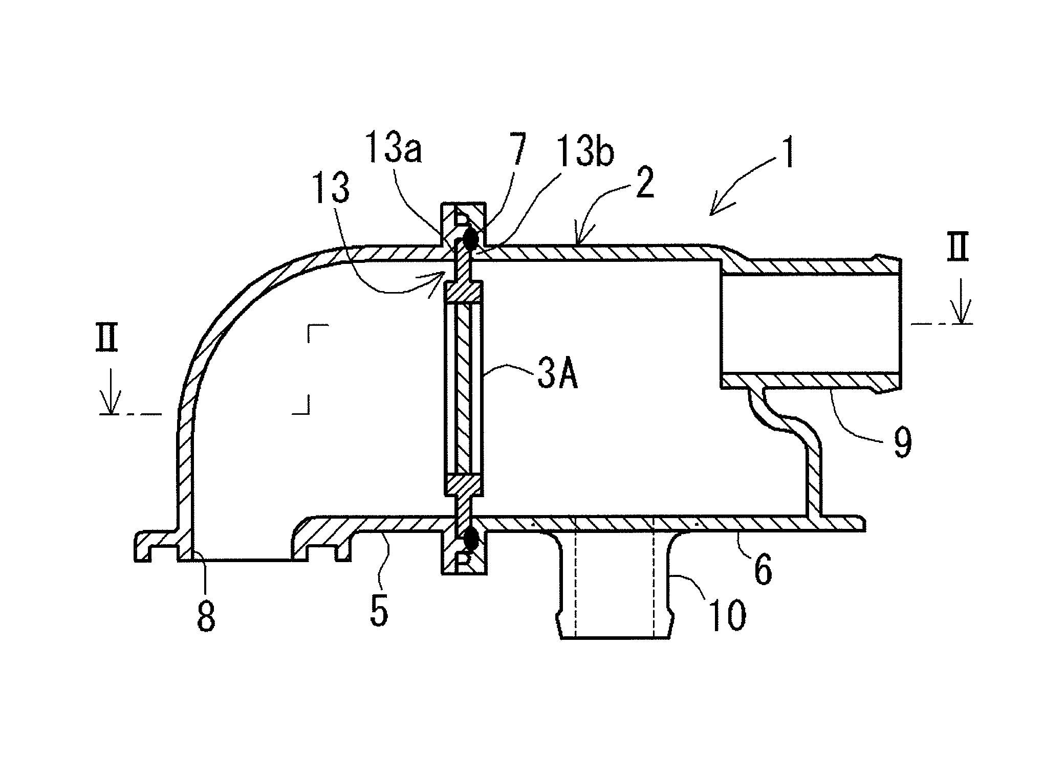
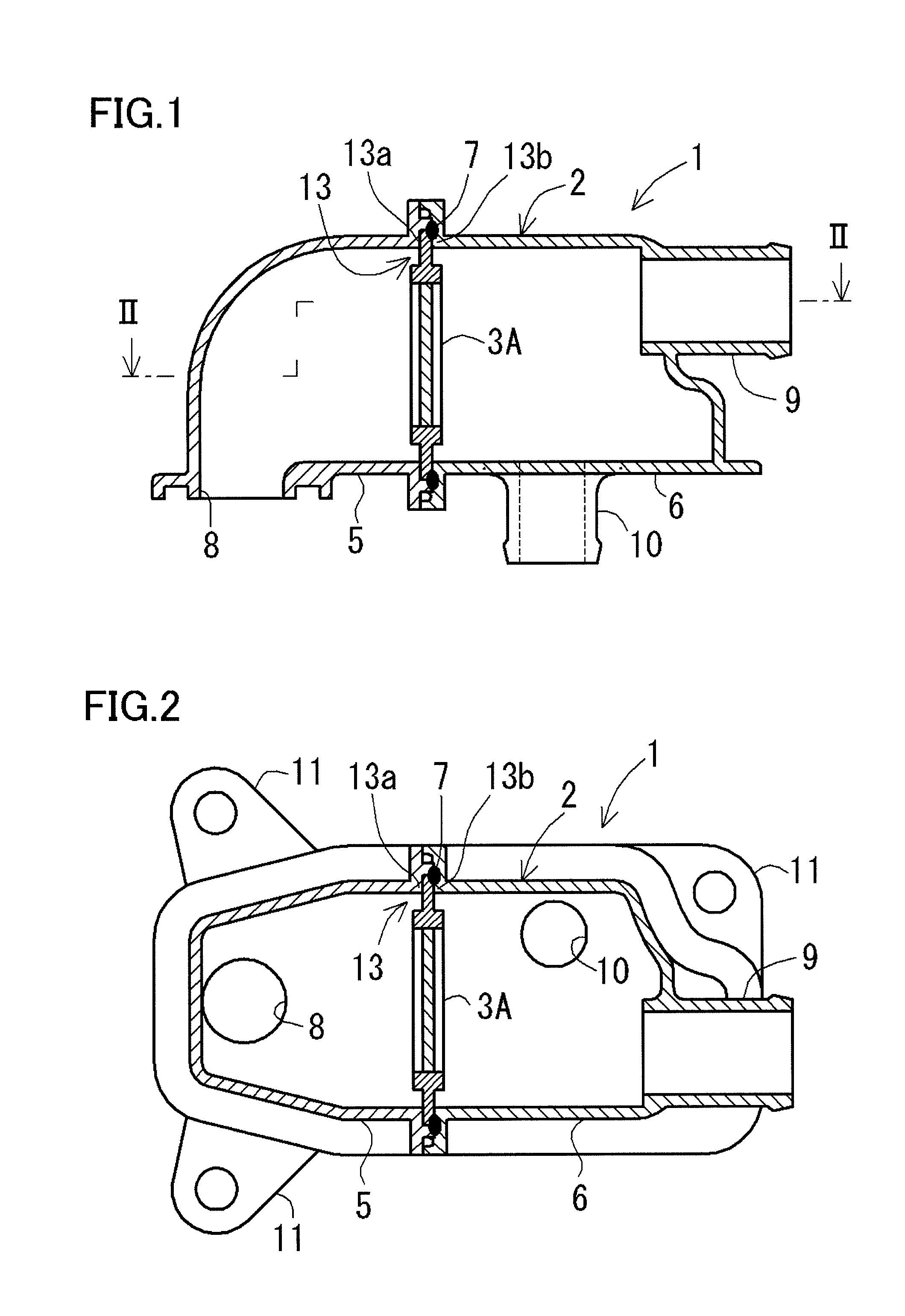
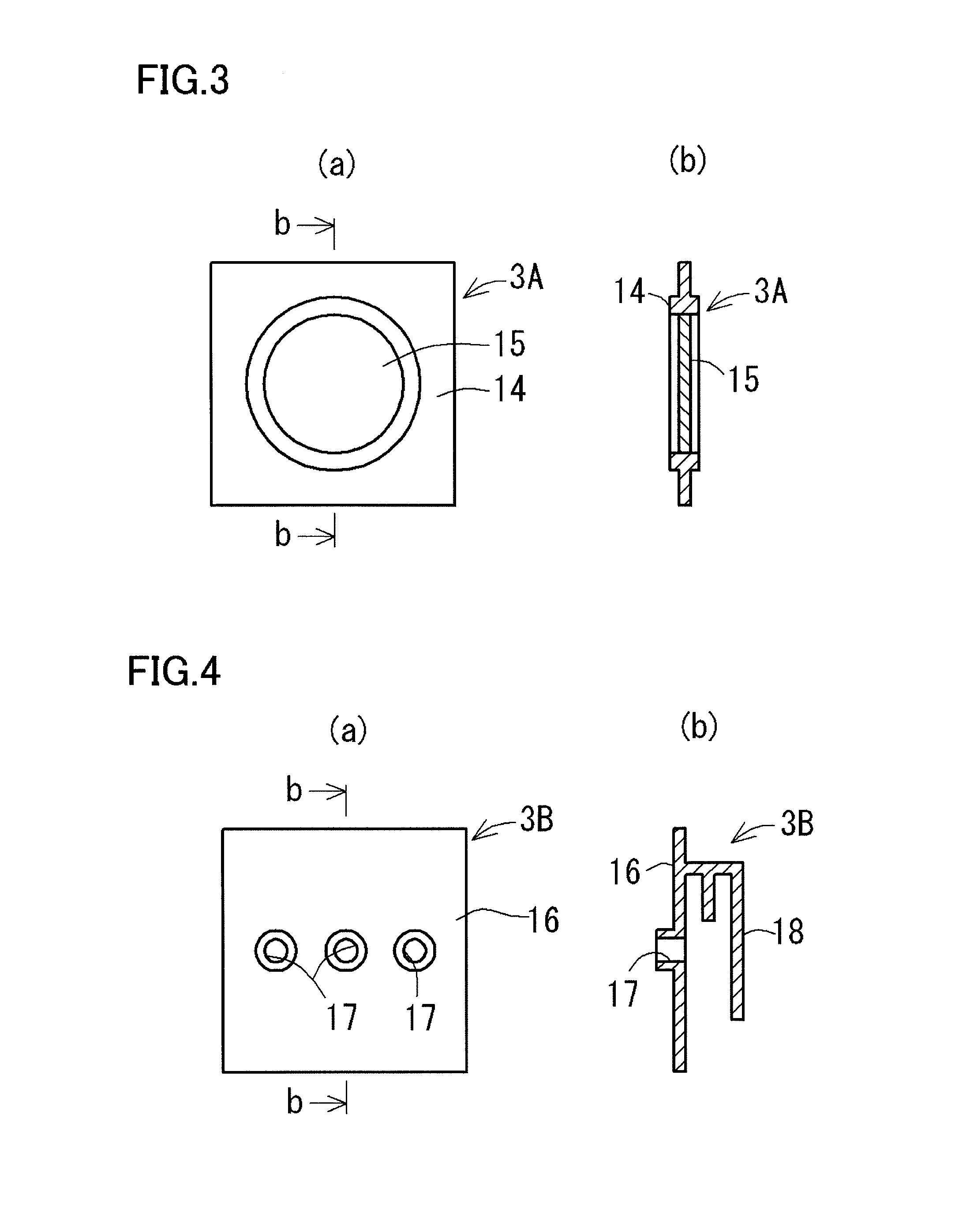
[0046]An oil separator 1 according to the present embodiment is an oil mist separator for capturing oil mist contained in blow-by gas generated in an engine (not shown), as shown in FIGS. 1 and 2. The oil separator 1 includes a housing 2 provided independently of a body of the engine and a gas-liquid separation unit 3A (3B, 3C) which is provided in the housing 2 and separates the blow-by gas into a gas component and an oil component.
[0047]The housing 2 includes first and second cases 5 and 6 made of resin, whose connecting circumferential surfaces 5a and 6a (see FIG. 6) are connected with each other at a welded portion 7 using vibration welding. The first case 5 has a hole-shaped lead-in port 8 which is provided on the upstream side of the gas-liquid separation unit 3A (3B, 3C) and through which blow-by gas is led in. Further, the second case 6 has a tube-shaped lead-out port 9 which is provided on the downstream side of the gas-liquid separation un...
second embodiment
(1) Configuration of Oil Separator
[0059]An oil separator 21 according to the present embodiment is an oil mist separator for capturing oil mist contained in blow-by gas generated in an engine (not shown), as shown in FIGS. 8 and 9. The oil separator 21 includes a housing 22 provided independently of a body of the engine and a gas-liquid separation unit 23A (23B, 23C) which is provided in the housing 22 and separates the blow-by gas into a gas component and an oil component.
[0060]The housing 22 includes first and second cases 25 and case 26 made of resin, whose connecting circumferential surfaces 25a and 26a (see FIG. 13) are connected with each other at a welded portion 27a using vibration welding. The first case 25 has a hole-shaped lead-in port 28 which is provided on the upstream side of the gas-liquid separation unit 23A (23B, 23C) and through which blow-by gas is led in and a tube-shaped drain port 30 which is provided on the downstream side of the gas-liquid separation unit 23...
PUM
 Abstract
Description
Claims
Application Information