Gripping Element And Gripper Input Module For A Haptic Input System

a technology of input module and gripper, which is applied in the field of gripper input module for haptic input system, can solve the problems of complex system, system becoming ever more complicated, and structural problems already occurring, and achieves the effect of simple cleaning and simple sterilization

Active Publication Date: 2014-06-19
KARL STORZ GMBH & CO KG
View PDF2 Cites 29 Cited by
  • Summary
  • Abstract
  • Description
  • Claims
  • Application Information

AI Technical Summary

Benefits of technology

[0015]In accordance with one aspect there is provided a gripping element and a corresponding adapter element, which together form a gripper input module, which is a component of a haptic input system for controlling at least one object, which gripping element and corresponding adapter element enable ergonomic actuation of a haptic input system, particularly in respect of gripping movements, or gripper-like movements, wherein, in particular, secure control and movement should be made possible for the user in the process. Furthermore, in accordance with another aspect, the device should preferably also be simple to clean, in particular, to be simple to sterilize at the exposed gripping and contact regions with a user.

Problems solved by technology

Apart from the comparatively complicated procedure of having to provide each finger individually with a thimble, the design of the combination device described in U.S. Pat. No. 7,480,600 B2 leads to a complicated system of rods being present.
This system becomes ever more complicated with increasing numbers of fingers to be identified, and so structural problems may also already occur in the case of three or more fingers.
The gripping elements arranged on this handle are, as a result of the provision with these respectively mechanical components, furthermore disadvantageous to the extent that these elastic / mechanical components are subjected to a certain amount of wear and tear, making replacement necessary from time to time.
However, as a result of the secure integration into the handle in this device, this is connected with much effort.
In addition to the comparatively bad ergonomic design and the aforementioned aspects in relation to wear and tear, comparatively complicated cleaning / sterilizing is furthermore required due to the depicted embodiment of the handle if the device is to be used in the vicinity of an operation site.
An application of a general sheath would not redress this in this case either, since this once again reduces the user comfort of such a device.
The aforementioned disadvantages of unsafe operation, possible slippage and difficult control due to inexpedient ergonomic conditions are not removed by the use of such a tactile glove either.
Although, purely theoretically, the haptic input systems described above in an exemplary manner enable the transmission of gripper information to a target system, this is however brought about by means of e.g. a freely suspended hold of the hand and, individually for each finger, by a complicated connection of the hand to the individual haptic input systems in U.S. Pat. No. 7,480,600 B2 or by means of a more stylus-shaped arrangement in U.S. Pat. No. 7,411,576 B2 and US 2008 / 0154246 A1, which arrangement is likewise unsuitable for targeted controlled gripper-like movement.
As a result of the comparatively non-ergonomic actuation, there can easily be slippage or shifting from the actual position in both devices, which may be fatal, particularly in difficult applications such as e.g. a surgical intervention or complicated mechanical interventions.
Moreover, the above-described devices establish the connection to the user by means of elements securely arranged on the devices, like e.g. in U.S. Pat. No. 7,480,600 B2, US 2008 / 0154246 A1 and US 2008 / 0167662 A1, or by means of elements with an at least comparatively complicated design, which are not suitable for in-depth cleaning either, like in U.S. Pat. No. 7,411,576 B2.
As a result, these devices are disadvantageous for uses in the medical sector, particularly in surgical interventions in the vicinity of the operation site.

Method used


Image

  • Gripping Element And Gripper Input Module For A Haptic Input System
  • Gripping Element And Gripper Input Module For A Haptic Input System
  • Gripping Element And Gripper Input Module For A Haptic Input System

Examples


Embodiment Construction

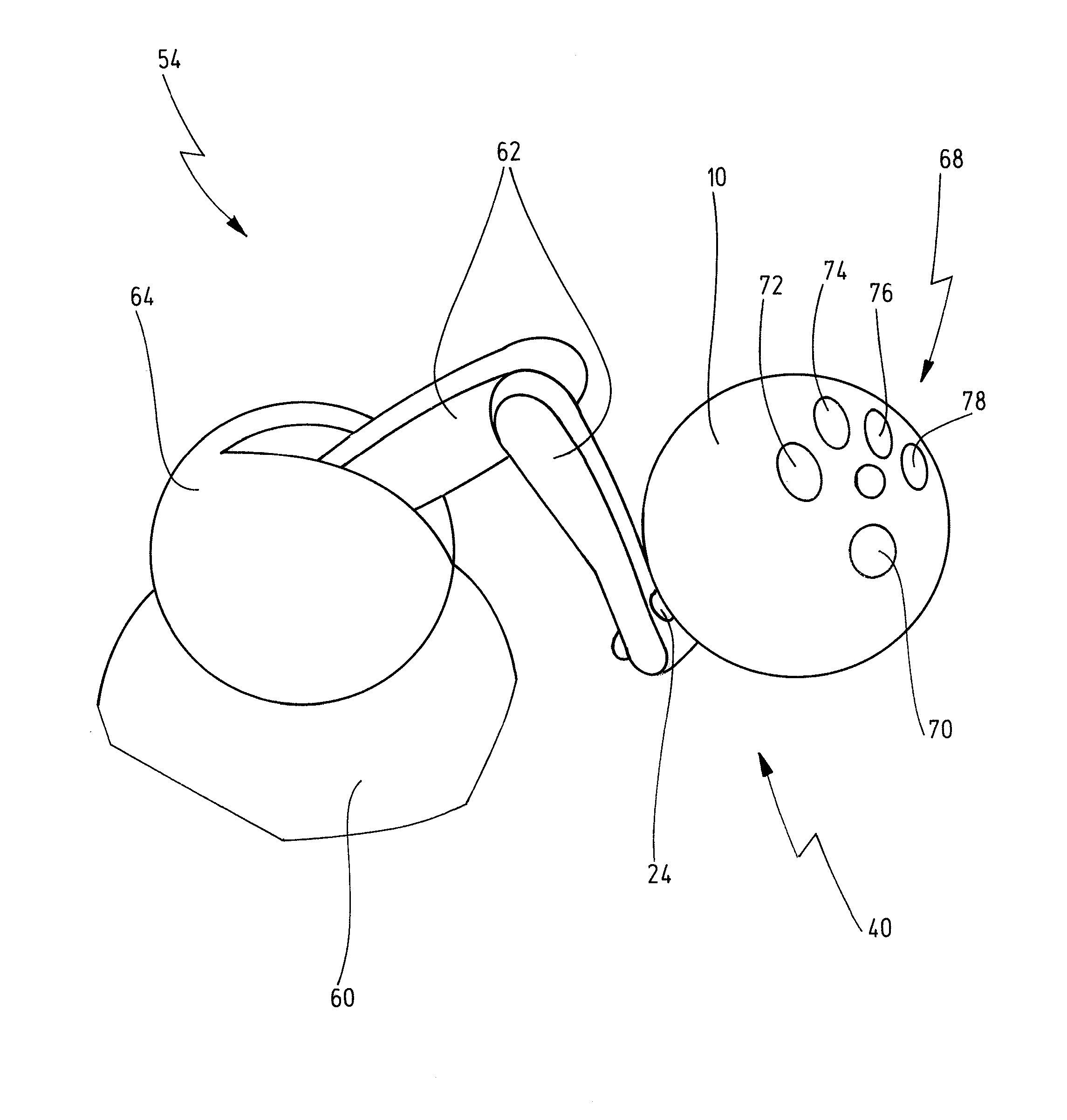
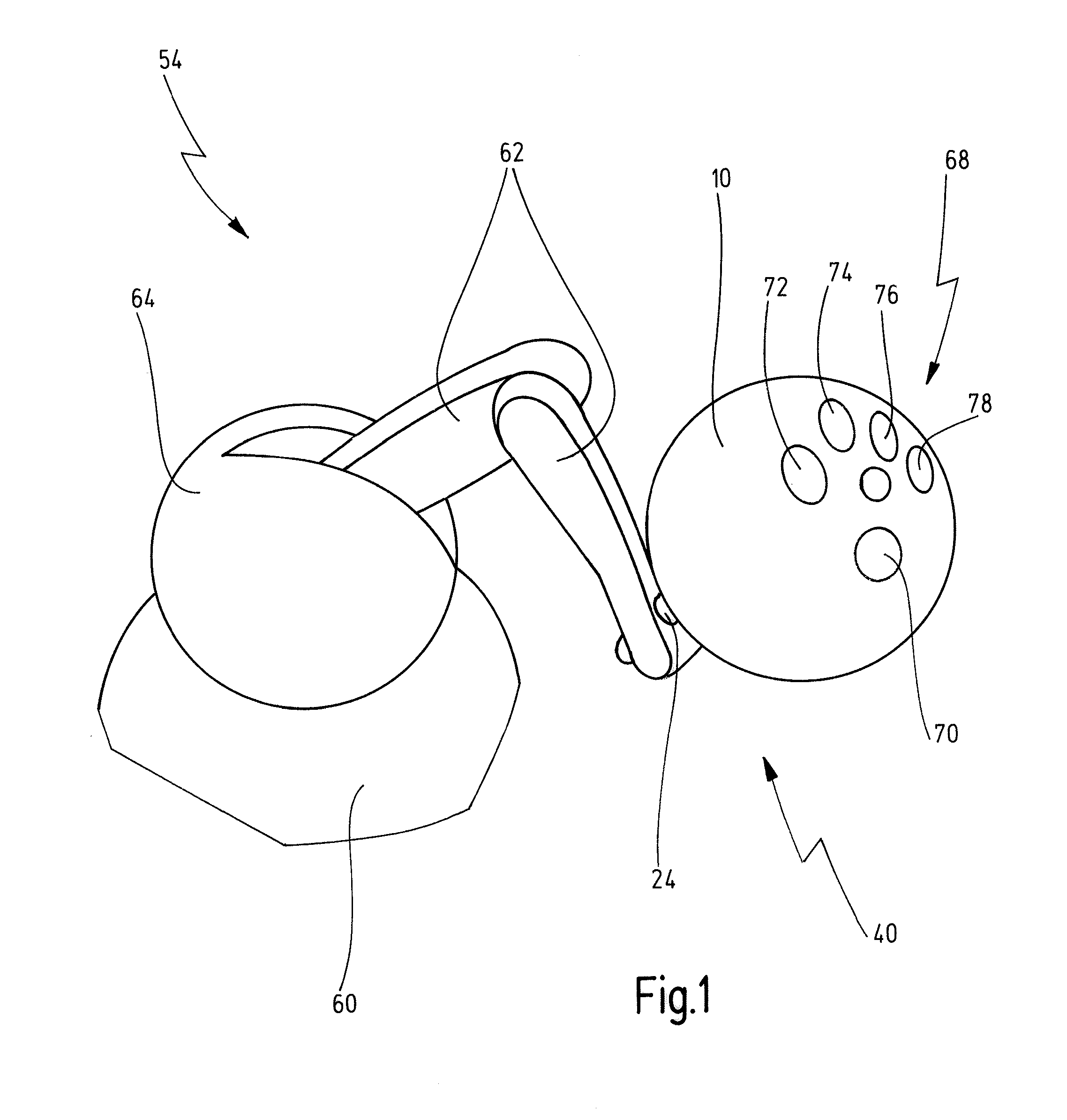
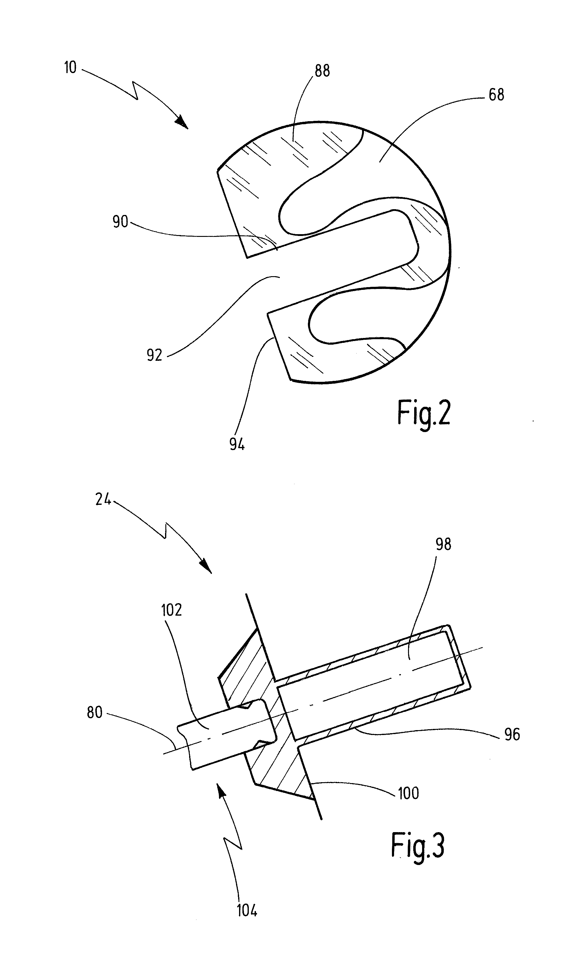
[0089]A gripping element according to one aspect is shown and described in conjunction with FIGS. 1, 2 and 4 to 11 and is respectively denoted by reference signs 10, 12, 14, 16, 18 and 20 in its entirety. An adapter element according to one aspect is shown and described in conjunction with FIGS. 1, 3, 4 to 8 and 11 and is respectively denoted by reference signs 24, 26, 28, 30 and 32 in its entirety. A gripper input module according to one aspect is shown in more detail and described in conjunction with FIGS. 1, 4 to 8 and 11 and is respectively denoted by reference signs 40, 42, 44, 46 and 48 in its entirety. A haptic input system according to one aspect is shown and described in more detail in conjunction with FIGS. 1, 4 and 12 and is denoted by reference sign 54 in its entirety. A medical instrument system according to one aspect is shown in more detail and described in conjunction with FIG. 12 and is denoted by reference sign 58 in its entirety.

[0090]A haptic input system 54, com...


PUM


Abstract

A gripping element for arrangement on an adapter element in order to form a gripper input module for a haptic input system for controlling an object, including a receptacle for holding at least two fingers of a user therein, wherein, at least in one portion, the receptacle has a functional connection to at least one sensor means, and at least one connection element for arranging the gripping element on the adapter element, wherein the receptacle is configured such that movement information of a movement of at least one finger of the user in the receptacle can be detected by the sensor means and hence the movement information can be transmitted for controlling the at least one object. There is also disclosed a corresponding adapter element, a gripper input module consisting of a gripping element and adapter element, and also to a haptic input system and medical instrument system.

Description

FIELD OF THE INVENTION[0001]The present invention relates to aspects of a gripping element for arrangement on an adapter element or an adapter element for detachably holding a gripping element, respectively in order to form a gripper input module for a haptic input system for controlling at least one object. Furthermore, the present invention relates aspects of a corresponding gripper input module, a haptic input system and a medical instrument system.BACKGROUND OF THE INVENTION[0002]Haptic input systems are used in the industrial and medical sector, but also in the end-user sector, in order to transmit the movement of a user, in particular of at least one hand, to another system. These other systems can be directly actuatable devices, such as e.g. medical instruments, machines, vehicles which can be controlled remotely, robots or the like. Alternatively, the information contained by the input into these haptic input systems can also be implemented in (purely) computer-related appli...

Claims


Application Information

Patent Timeline
Patent Type & Authority Applications(United States)
IPC IPC(8): B25J13/02A61B19/00
CPCA61B19/2203B25J13/025G06F3/016G06F3/0346A61B34/30Y10T74/20305A61B1/00
Inventor ABRI, OMIDSCHRADER, STEPHANFORSTER, JONAS
Owner KARL STORZ GMBH & CO KG
Why Eureka
Try Eureka