

Headgear apparatus for nasal interface
a headgear and nasal interface technology, applied in the field of headgear, can solve the problems of increased strapping force, reduced patient comfort, and dislodged mask parts of respiratory patient interface devices,
- Summary
- Abstract
- Description
- Claims
- Application Information
AI Technical Summary
Benefits of technology
Problems solved by technology
Method used
Image

Examples
first embodiment
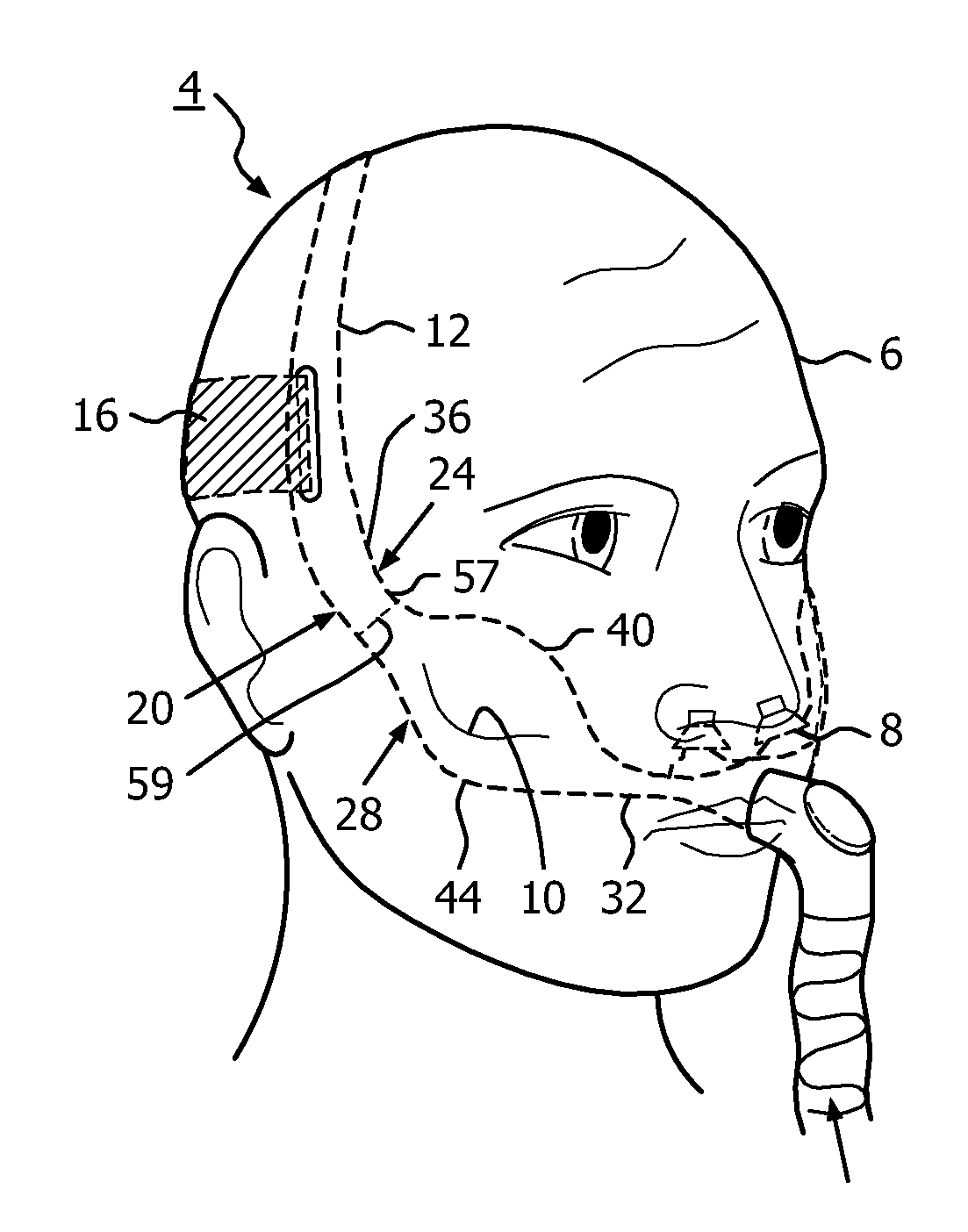
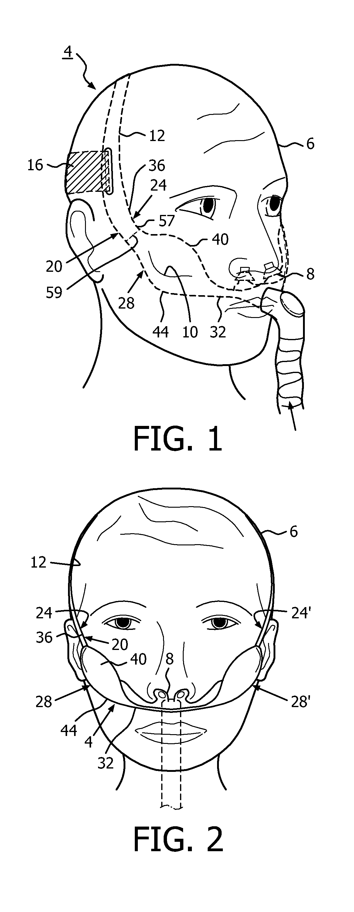
[0052]An improved headgear 4 in accordance with the present invention is depicted in FIG. 1 as being situated on a patient 6 and as supporting a nasal pillow interface 8 engaged with the nostrils of patient 6. As is generally understood, patient 6 has a zygomatic bone or cheekbone that is depicted schematically at the numeral 10 and which is a facial bone. Headgear 4 advantageously interacts with zygomatic bone 10 in order to support and maintain the position of headgear 4 and nasal pillow interface 8 with respect to patient 6. More particularly, at least a portion of headgear 4 interacts with the soft tissue of the face of patient 6 in the region of zygomatic bone 10. Headgear 4 and nasal pillow interface 8 can together be referred to as a headgear apparatus.
[0053]While the headgear apparatus employs nasal pillow interface 8 to provide fluid communication with the breathing passages of patient 6, it is understood that nasal pillow interface 8 is merely an example of one such patien...
third embodiment
[0071]An improved headgear 104 in accordance with the present invention is depicted generally in FIGS. 9 and 10. Headgear 104 supports a nasal pillow interface 108 on a patient and includes a parietal support 112, an occipital support 116, and a zygomatic support 120. Zygomatic support 120 includes a zygomatic strap 124 that carries a zygomatic brace 128. Notably, zygomatic brace 128 is in the form of a zygomatic loop 130 that interacts with the zygomatic bone of the patient. More particularly, zygomatic loop 130 is situated between an anterior portion 132 of zygomatic strap 124 and a posterior portion 136 of zygomatic strap 124 and includes a cephalic element 140 and a caudal element 144. It can be understood that cephalic element 140 constitutes the cephalic, i.e., upper, segment of zygomatic loop 130, and caudal element 144 constitutes the caudal, i.e., lower, segment of zygomatic loop 130. The cephalic element 144 is situated cephalic to the crest of the zygomatic bone, and caud...
fourth embodiment
[0075]An improved headgear 204 in accordance with the present invention is depicted generally in FIGS. 11 and 12. Headgear 204 is depicted as supporting a nasal pillow interface 208 on a patient. Headgear 204 includes a parietal support 212 that is in the form of a conventional fabric strap that is connected with a zygomatic / occipital support 218 that is co-formed as a single piece member. Zygomatic / occipital support 218 can be said to include an occipital strap 222 and a zygomatic strap 224, with zygomatic strap 224 having a zygomatic brace 228 in the form of thickened region anterior to a zygomatic / occipital loop 234 that spans occipital and zygomatic straps 222 and 224.
[0076]Zygomatic / occipital loop 234 directs forces along a cephalic element 240 and a caudal element 244 thereof to provide support for nasal pillow interface 208 while maintaining a desirable position of nasal pillow interface 208 with respect to the zygomatic bone of the patient. More particularly, zygomatic strap...
PUM
 Abstract
Description
Claims
Application Information