Waler Strongback Clamp with Cam

a technology of strongback clamping and clamping rod, which is applied in the direction of walls, building parts, construction, etc., can solve the problems of cumbersome and laborious methods, cumbersome and laborious inventions, and about 2 kilograms of weight, and achieves the effects of less expensive, light weight and easy installation

Active Publication Date: 2014-06-19
FAB-FORM IND LTD
View PDF10 Cites 4 Cited by
  • Summary
  • Abstract
  • Description
  • Claims
  • Application Information

AI Technical Summary

Benefits of technology

[0015]As the cam is rotated counter clock wise by hand, the radius is increased so that the surface of the cam tightens on the strongback and subsequently on the waler. At the same time, the outside edge or lip of the cam increases by one half inch in diameter, thereby preventing the strongback from sliding off the cam.
[0016]The invention reduces the difficulties and disadvantages of the prior art by providing a waler-strongback bracket which is light weight, easy to install and less expensive. The waler-strongback clamp with cam weights only 1.8 pounds which is more than 40 times lighter than the conventional ICF vertical brace. As well, the clamp is less than one tenth the cost of the conventional ICF brace.

Problems solved by technology

However this method is cumbersome and labor intensive.
Again this invention is cumbersome and labor intensive.
There are several disadvantages with this system: first, each brace (beam and kicker) weights about 65 pounds, therefore the total weight is about 2,600 pounds for a typical foundation.
Fourthly, the method has difficulty adapting top uneven wall heights as the beams are typically all the same length.
Finally the system is expensive, which each brace costing about $250, or $10,000 for a typical foundation.
This method of holding the horizontal waler is complex with many parts and very labor intensive to install and strip after the pour.

Method used


Image

  • Waler Strongback Clamp with Cam
  • Waler Strongback Clamp with Cam
  • Waler Strongback Clamp with Cam

Examples


Embodiment Construction

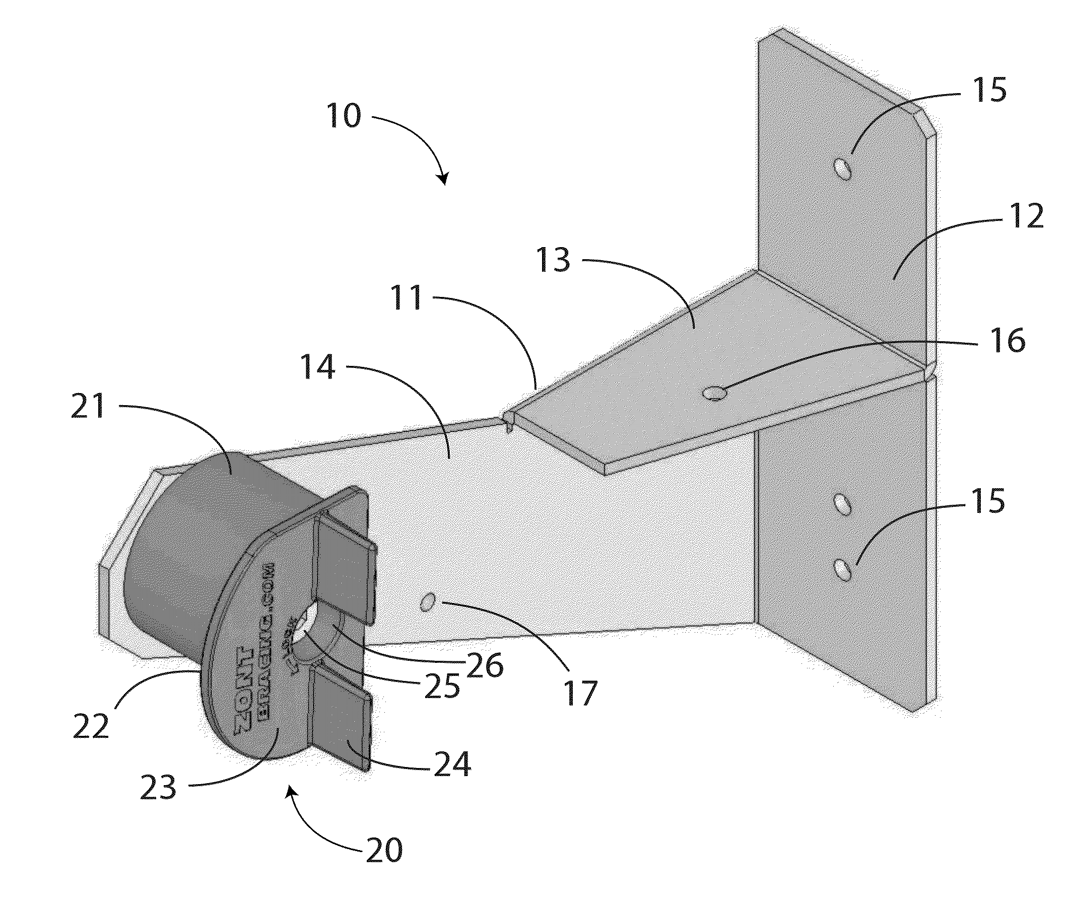
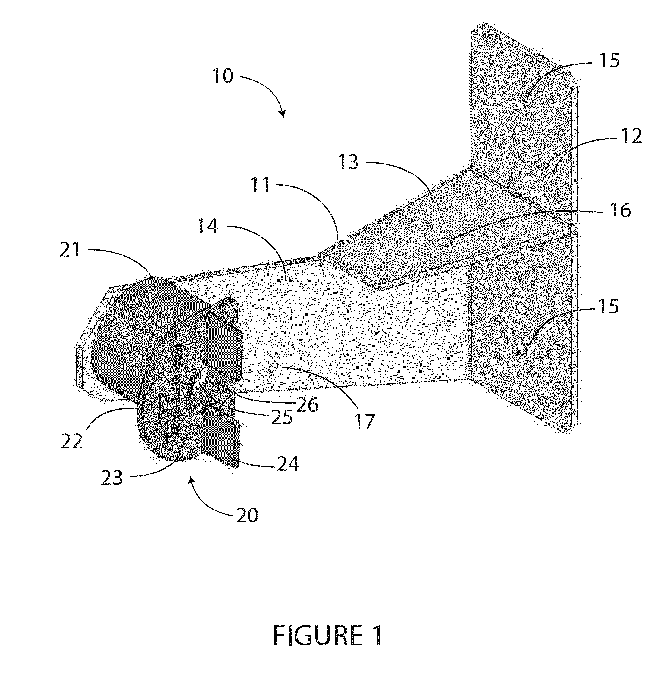
[0026]FIG. 1 is a simplified perspective view showing the preferred embodiment of the waler strongback clamp with cam (10). It consists of a body (11) made from 10 gauge sheet metal, a plastic cam (20) and a shoulder bolt (25) attaching cam to body (11).

[0027]The clamp body (11) consists of a substantially vertical member (12), a substantially horizontal member (13) extending from approximately the midpoint of vertical member (12), and a second vertical member (14) extending from and perpendicular to both the vertical member (12) and horizontal member (13). This second vertical member (14) extends a distance past horizontal member (13). A hole is located at the end of the second vertical member (14) away from the vertical member (10), so that a cam (20) is attached using a shoulder bolt (25) and nut. Typically the body (11) would be made from a single piece of sheet metal, bent at 90 degrees to produce the shape as shown in FIG. 1.

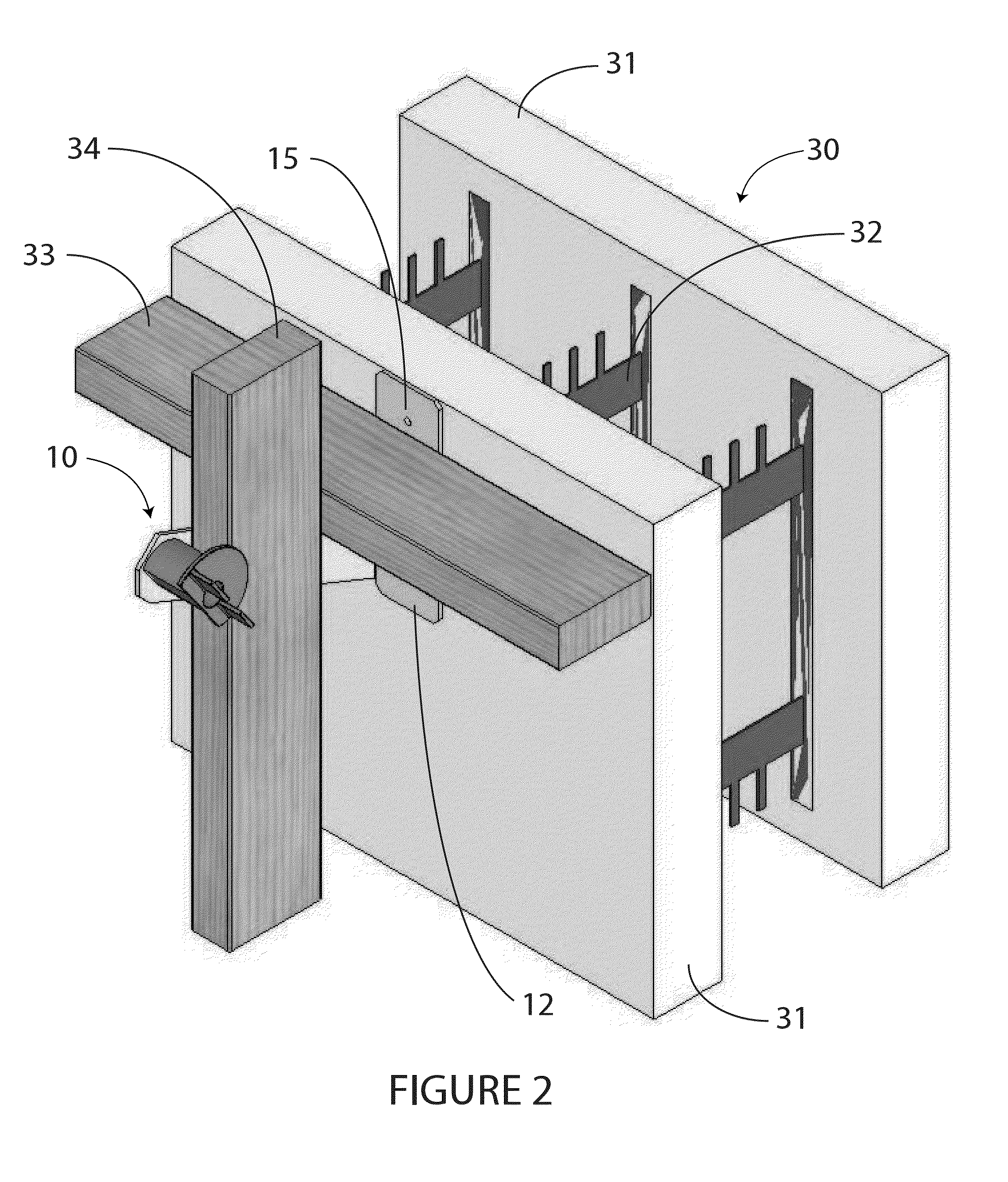
[0028]FIG. 2 is a simplified perspective view showin...


PUM


Abstract

A waler and strongback bracket used clamp a waler and strongback to the face of a concrete wall form. The bracket consists of a metal body with a vertical surface for attachment to the wall form, a horizontal surface for supporting the waler, a vertical surface for the strongback and a cam that when rotated locks both the waler and strongback against the concrete wall form.

Description

CROSS REFERENCE TO RELATED APPLICATIONS[0001]This application claims priority under 35 U.S.C 119(e) to Richard Fearn's U.S. Provisional Patent Application No. 61 / 701,640 filed on Sep. 15, 2012 entitled INSULATING CONCRETE FORM WALER BRACKET WITH CAM, the disclosure of which is incorporated herein by reference.FIELD OF THE INVENTION[0002]This invention relates generally to an alignment apparatus for concrete wall forms which aligns the wall in both the horizontal and vertical directions. This apparatus is restricted to those wall forms where the hydraulic concrete pressures are taken by the wall form itself, for example with insulating concrete forms.DISCUSSION OF RELATED ART[0003]Wall forming systems for concrete have been in use for many years, and generally have consisted of plywood panels with steel ties to restrain the panels parallel to each other the wall distance apart. Then 2×4 horizontal walers align the plywood panels horizontally. Waler brackets are used to clamp the 2×4 ...

Claims


Application Information

Patent Timeline
Patent Type & Authority Applications(United States)
IPC IPC(8): E04G17/07
CPCE04G17/07B25B5/04B25B5/08E04B2002/8688E04G17/02E04G17/14
Inventor FEARN, RICHARD N.
Owner FAB-FORM IND LTD
Why Eureka
Try Eureka