Electronic device and control method thereof

Inactive Publication Date: 2014-06-19
RISO KAGAKU CORP
View PDF3 Cites 12 Cited by
  • Summary
  • Abstract
  • Description
  • Claims
  • Application Information

AI Technical Summary

Benefits of technology

[0009]The present invention has been made in view of the above, and an object thereof is to provide

Problems solved by technology

In contrast with this, when the operator tries to operate the target object so as not to hide the screen by his/her hand, unnatural movement of the hand may be forced.
However, even in this case, a part of the screen is hidden by a pen tip or the operator's hand, which may cause deteri

Method used


Image

  • Electronic device and control method thereof
  • Electronic device and control method thereof
  • Electronic device and control method thereof

Examples


Example

[0021]Hereinafter, an embodiment of the present invention will be explained with reference to drawings. A same or an equal symbol is given to a same or an equal portion or component through each drawing.

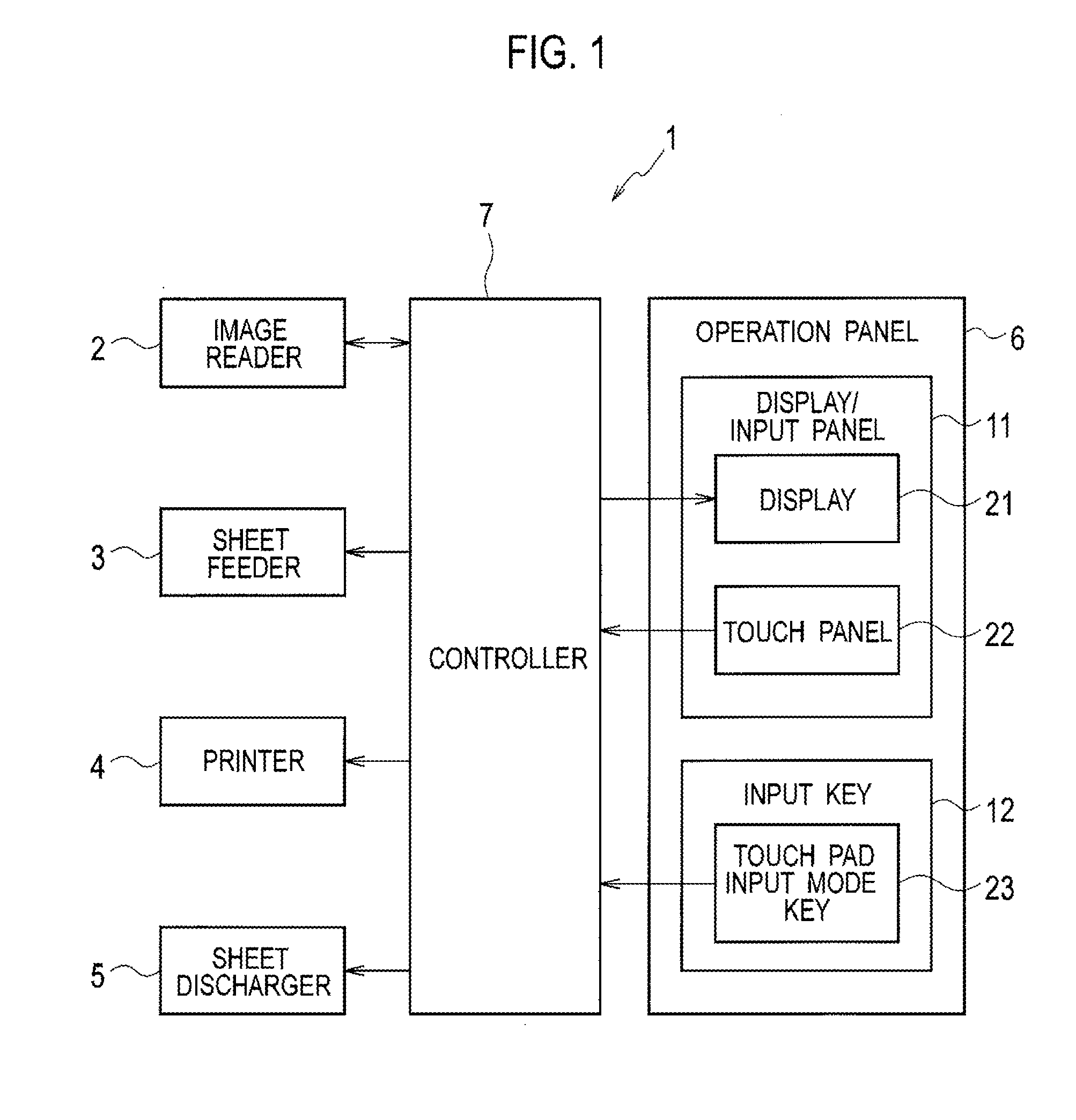
[0022]FIG. 1 is a block diagram showing a configuration of a printing machine pertaining to the embodiment of the present invention. As shown in FIG. 1, a printing machine 1 pertaining to the embodiment includes: an image reader 2; a sheet feeder 3; a printer 4; a sheet discharger 5; an operation panel 6; and a controller 7. It is to be noted that the printing machine 1 corresponds to an electronic device in claims.

[0023]The image reader 2 optically reads an image of an original, and generates image data.

[0024]The sheet feeder 3 feeds sheet stacked on a sheet feed tray to the printer 4.

[0025]The printer 4 performs printing on sheet fed by the sheet feeder 3 based on the image data generated by the image reader 2 or image data input to the printing machine 1 from an external terminal....


PUM


Abstract

A printing machine includes: a display that displays an input screen; a touch panel that is arranged on the display and detects contact operation by an operator; and a controller that displays an operation region in the input screen, and controls operation processing for the input screen based on the contact operation to the touch panel with respect to the operation region.

Description

BACKGROUND OF THE INVENTION[0001]1. Field of the Invention[0002]The present invention relates to an electronic device provided with a touch panel.[0003]2. Related Background of the Invention[0004]Conventionally, an electronic device provided with a touch panel has been known. In such an electronic device, an operator can perform input operation to a screen by touching a position of a target object in the screen with a finger or the like (for example, refer to Patent Document 1).PRIOR ART DOCUMENTPatent Document[0005][Patent Document 1] U.S. Pat. No. 7,479,949SUMMARY OF THE INVENTION[0006]Since in the operation to the touch panel, a hand is moved to the whole screen to operate the target object in the screen with the finger or the like, the above-described object and vicinity thereof may be hidden by the operator's hand. In contrast with this, when the operator tries to operate the target object so as not to hide the screen by his / her hand, unnatural movement of the hand may be force...

Claims


Application Information

Patent Timeline
IPC IPC(8): G06F3/041
CPCG06F3/0412G06F3/0488G06F2203/04803
Inventor ESAKI, YASUHIRO
Owner RISO KAGAKU CORP
Why Eureka
Try Eureka