
Image forming apparatus

a technology forming chamber, which is applied in the direction of digital output to print units, visual presentations, instruments, etc., can solve the problems of image quality degradation, thermal deterioration of apparatus parts, and increase in temperature of image forming apparatus

Active Publication Date: 2014-06-19
KONICA MINOLTA INC
View PDF2 Cites 15 Cited by
  • Summary
  • Abstract
  • Description
  • Claims
  • Application Information

AI Technical Summary

Benefits of technology

The patent text discusses a solution for problems related to temperature rise in printing apparatus caused by multiple prints. The solution involves a delay process that slows down the printing speed by suspending the execution of print operation when the temperature in the apparatus exceeds a set level or by increasing the time interval between sheet transfers when the number of prints exceeds a set number. This prevents temperature rise and solves the related problems.

Problems solved by technology

However, by continually processing print operation at high speed, the temperature of the image forming apparatus tends to increase.
This may cause problems such as the thermal deterioration of apparatus parts, the image quality degradation as a result melting and subsequent sticking of the toner in a developer, and the like.
Therefore, heat accumulated in the recording sheets cannot be dissipated easily, which increases the risk of tacking.
Unfortunately, the delay process described above slows the processing speed of print operation, which decreases the print operation productivity.
The decrease in print operation productivity is especially notable when the duration of the delay process is prolonged.
Yet, the shorting of sheet transfer intervals may lead to a temperature rise in the apparatus, which may result in another delay process to be executed during the print operation.

Method used


Image

  • Image forming apparatus
  • Image forming apparatus
  • Image forming apparatus

Examples


Embodiment Construction

[0041]The following describes an embodiment of an image forming apparatus according to the present invention, by way of a tandem-type digital color printer (hereinafter, simply “printer”).

[1] Structure of Printer

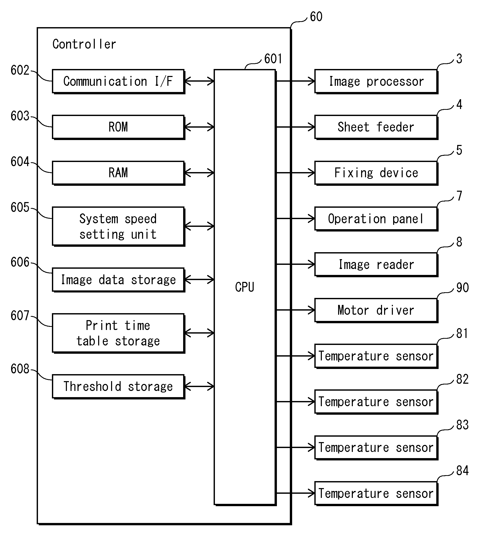
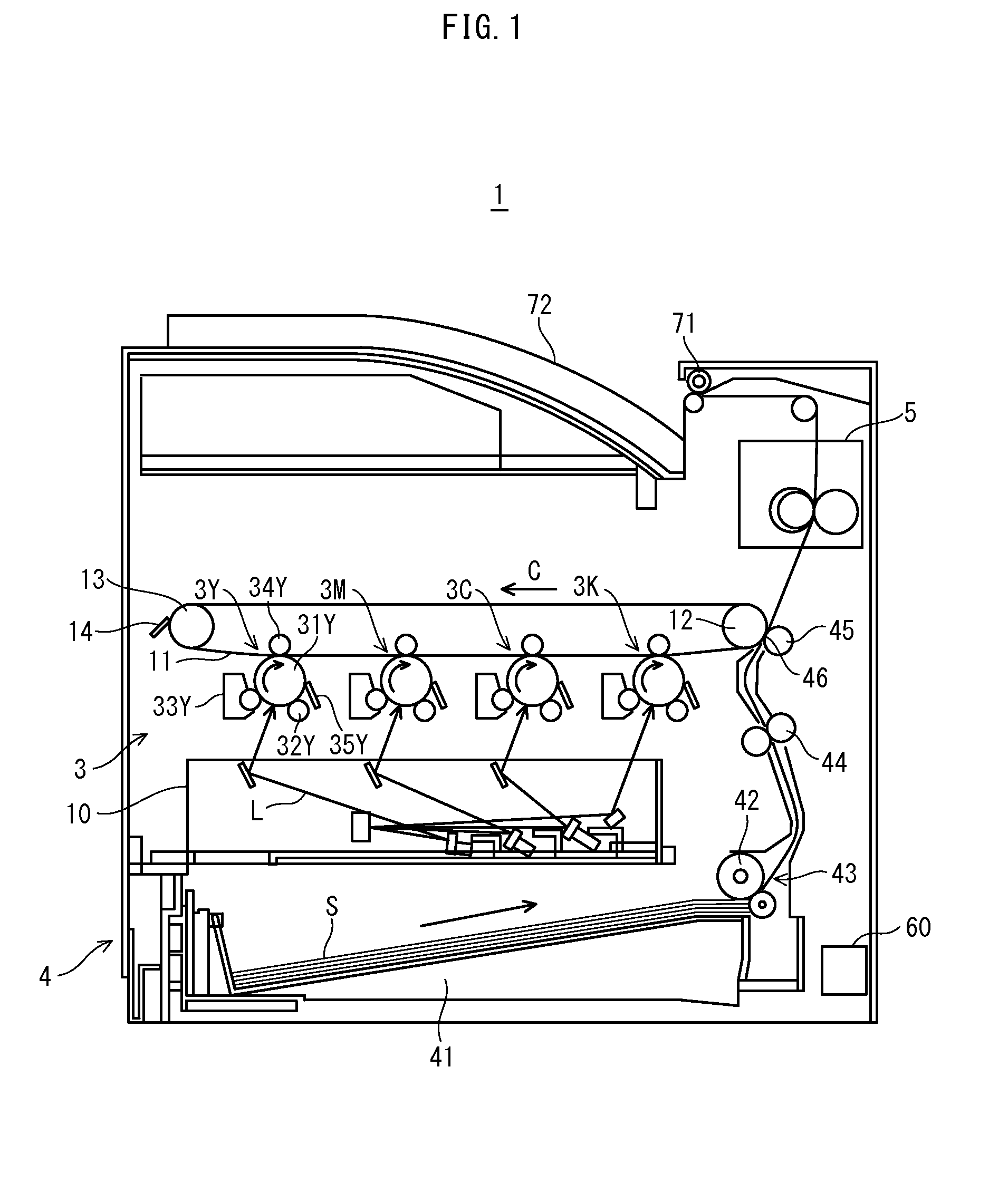
[0042]The following describes the structure of a printer according to the present embodiment. FIG. 1 is a view showing the structure of the printer according to the present embodiment. As shown in the figure, the printer 1 includes an image processer 3, a sheet feeder 4, a fixing device 5, and a controller 60.

[0043]The printer 1 is connected to a network (such as LAN) to receive requests for executing print operation from an external terminal device (not illustrated) or from an operation panel 7 (shown in FIG. 4) having a non-illustrated display. Upon receipt of such a request, the printer 1 forms toner images of the respective colors of yellow, magenta, cyan, and black, and sequentially transfers the toner images to a recording sheet, so that a full-color image is formed on...


PUM


Abstract

An image forming apparatus executes a print job at an initial processing speed and switching the initial processing speed to a delayed processing speed lower than the initial processing speed upon detecting occurrence of a specific condition under which continuing the print job at the initial processing speed is determined not possible. The image forming apparatus acquires a print job targeted to be executed; estimates a processing time to be taken to complete the target print job at each of a plurality of processing speeds selected as candidates for the initial processing speed; and determines, as the initial processing speed, one of the candidate processing speeds that corresponds to the shortest processing time among the processing times estimated by the estimator.

Description

CROSS-REFERENCE TO RELATED APPLICATION[0001]This application is based on application No. 2012-276447 filed in Japan, the contents of which are hereby incorporated by reference.BACKGROUND OF THE INVENTION[0002](1) Field of the Invention[0003]The present invention relates image forming apparatuses, such as printers, copiers, and the like. In particular, the present invention relates to a technology for improving the productivity of print operation of an image forming apparatus that executes a delay process to provide a wait time by suspending the execution of print operation or by reducing the print speed. The delay process is executed with the aim of preventing the decrease in image quality or deterioration of the apparatus parts due to changes in temperature and the like in the image forming apparatus during print jobs.[0004]2) Description of the Related Art[0005]To improve the print operation productivity, image forming apparatuses, such as printers, copiers, and the like are requi...

Claims


Application Information

Patent Timeline
IPC IPC(8): G06F3/12
CPCG06F3/1254G06F3/1211G06K15/1823
Inventor HASEGAWA, SATOSHI
Owner KONICA MINOLTA INC
Learn More