Molding tools with interchangeable inserts to form a variety of parts with differing geometries from a single tool

a technology of inserts and tools, which is applied in the field of workpiece molding, can solve the problems of more laborious installation of showers, and achieve the effects of reducing the internal volume of heating/cooling plates, and facilitating the installation of shower pans

Inactive Publication Date: 2014-06-26
TILE REDI
View PDF34 Cites 12 Cited by
  • Summary
  • Abstract
  • Description
  • Claims
  • Application Information

AI Technical Summary

Benefits of technology

[0024]Some products which a manufacturer may want to vary the features (e.g. proportions, features, partial shapes, etc.) of, while still making all variations thereof from a single base tool, may nevertheless have some features that will remain constant across more than one, if not all, of the products. The surfaces of such products, and hence of the tool surfaces which make those products, may be viewed as being dividable into areas, each of which area has one or more features that will be common, at least to some extent, across all of the workpieces to be made from that particular tool (“feature-consistent areas”) such as drains, curbs, pitched (i.e. sloped) planar areas, barrier free entrances, splash walls, trenches, which may have different sizes and shapes. To simplify the assembly and disassembly process of such a tool, the various feature-consistent areas of the cavity and core halves of the tool can be viewed as “zones”. The tooling components for each zone of the tool are selected from a universe of potential components for each zone. Selection of different sets of components from the universe of potential components for any given zone results in a differently shaped workpiece, or at least permits the alteration of all or a portion of the zones and, hence, permits the workpiece, to be partially or completely varied without creating a partial or entirely new tool. A planar area / section of the surface of a shower pan floor is an example of such a zone. It is, in certain circumstances, desirable to create shower pan floors which have as much of the surface area thereof planar, or flat, so that is it easy to secure tile thereto. Floors having valleys therein require additional cutting of flooring material (e.g. ceramic tile) to follow the contours of the topography, making it more labor intensive to install a shower. The use of entire rows and columns of constant pitch inserts allows for the use (and, hence, fabrication) of the bare minimum number of such inserts to make any pan or prefabricated pan from a single tool.
[0026]It can be appreciated that, in the case of workpieces such as shower and bath components over which water is designed to flow with minimal obstruction and to be easily tiled, the transitions between zones should be smooth. To accomplish this in the circumstances where smooth transitions are desired, the inserts which abut an adjacent zone or zones are configured and arranged such that there is a smooth transition between such zones which facilitates the shower pan to be easily and properly tiled. In other cases, the transition between adjacent zones may be abrupt, as in the case of a consumer product having an irregular shape.
[0027]In another aspect of the invention, the inserts and heating plates are connected to thermally conductive mounting plates which are positioned between the respective heating / cooling plates of the tool and the inserts so that holes which are used to connect the inserts to the tool do not reduce the internal volume of the heating / cooling plates or pierce the heating / cooling plates. If used in any given application, the heating / cooling plate(s) of the cavity half of the tool are mounted to one side of the mounting plate(s) for the cavity half of the tool and the cavity side workpiece inserts on the other side of the mounting plate(s), and the heating / cooling plate(s) of the core half of the tool are mounted to one side of the mounting plate(s) for the core half of the tool and the core side workpiece inserts on the other side of the mounting plate(s), thereby permitting a limitless number of points connection for the core and cavity workpiece inserts without in any way impacting the respective heating plates.

Problems solved by technology

Floors having valleys therein require additional cutting of flooring material (e.g. ceramic tile) to follow the contours of the topography, making it more labor intensive to install a shower.

Method used


Image

  • Molding tools with interchangeable inserts to form a variety of parts with differing geometries from a single tool
  • Molding tools with interchangeable inserts to form a variety of parts with differing geometries from a single tool
  • Molding tools with interchangeable inserts to form a variety of parts with differing geometries from a single tool

Examples


Embodiment Construction

)

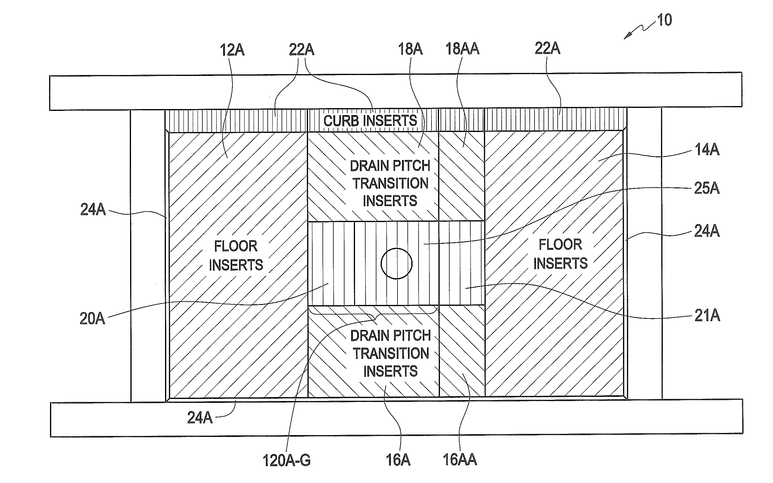
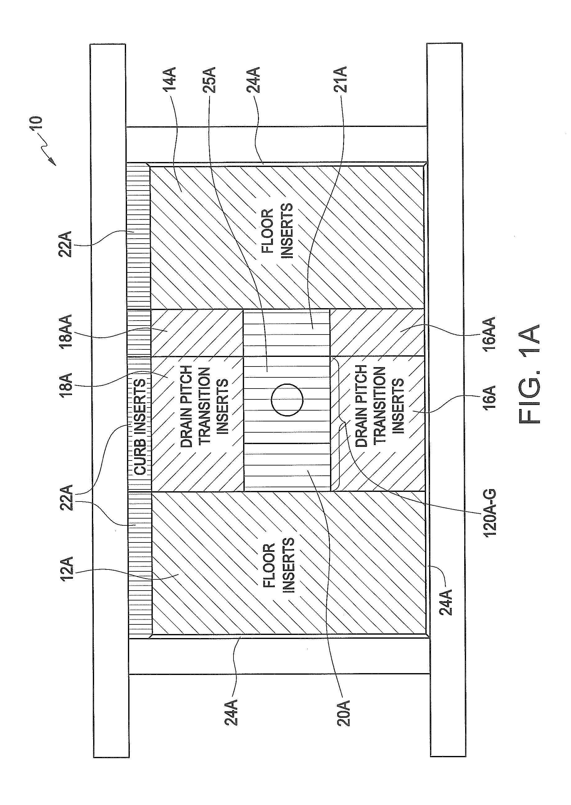
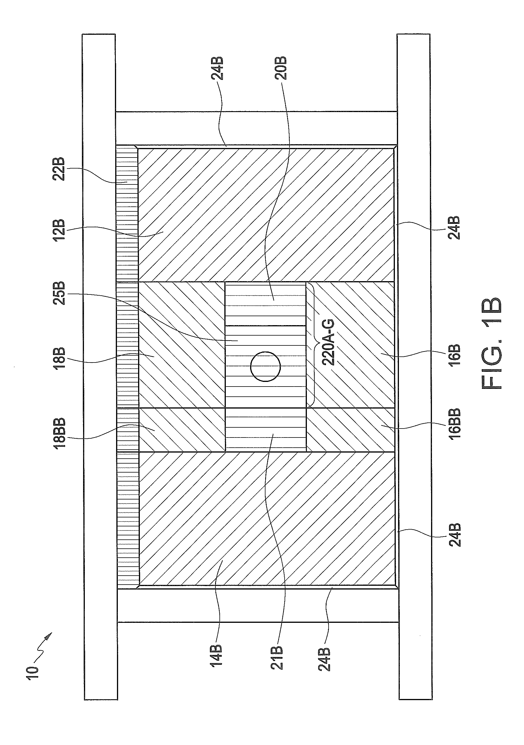
[0046]The inventive embodiments of my invention reside primarily in combinations of structural components and manufacturing, installation and use steps related to the creation of a variety of disparate molded workpieces, such as products made from injection molding processes, which can all be made from a single base tool using a series of strategically positioned, interchangeable inserts.

[0047]Accordingly, the apparatus components have been represented where appropriate by conventional symbols in the drawings, showing only those specific details that are pertinent to understanding the embodiments of the present invention so as not to obscure the disclosure with details that will be readily apparent to those of ordinary skill in the art having the benefit of the description herein.

[0048]In this document, relational terms, such as “first” and “second,”“top” and “bottom,” and the like, may be used solely to distinguish one entity or element from another entity or element without neces...


PUM

PropertyMeasurementUnit
areasaaaaaaaaaa
areasaaaaaaaaaa
areasaaaaaaaaaa

Abstract

A first aspect of the invention relates to the manufacture of disparate workpieces by the process of injection molding using a single base tool. The tool is made up of cavity and core halves, and each half is made up of separate, removable / interchangeable, inserts which, when combined in a particular order, form the workpiece-forming surface. All or any number of the inserts may be replaced with other inserts to alter the workpiece-forming surface and allow a large number of differently shaped workpieces (i.e. having different surface features and shapes) to be formed from a single base tool. In another aspect of the invention, the inserts are connected to respective thermally conductive cavity and core mounting plates, which are in turn connected to respective cavity and core heating / cooling plates so that insert-mounting holes need not be made in the heating / cooling plates.

Description

CROSS-REFERENCE TO RELATED APPLICATIONS[0001]This application is a continuation-in-part of co-pending application Ser. No. 13 / 453,779 filed Apr. 23, 2012. This application is also a continuation-in-part of co-pending U.S. application Ser. No. 13 / 351,842 filed on Jan. 17, 2012, which is a continuation of U.S. application Ser. No. 12 / 463,803 filed on May 11, 2009, now U.S. Pat. No. 8,112,831, which is a continuation-in-part of U.S. application Ser. No. 11 / 724,913 filed Mar. 17, 2007, now U.S. Pat. No. 8,141,182. This application is also a continuation-in-part of co-pending U.S. application Ser. No. 13 / 402,704 filed on Feb. 22, 2012, which was a continuation of U.S. application Ser. No. 11 / 724,913 filed on Mar. 17, 2007, now U.S. Pat. No. 8,141,182, which was commonly filed with the following U.S. patent application Ser. No. 11 / 724,873 now abandoned; U.S. patent application Ser. No. 11 / 724,914 filed Mar. 17, 2007, now U.S. Pat. No. 8,141,183; U.S. patent application Ser. No. 11 / 725,113...

Claims


Application Information

Patent Timeline
Patent Type & Authority Applications(United States)
IPC IPC(8): B29C45/26B29C67/24
CPCA47K3/40B29C45/14065B29C45/2673B29C67/246B29C2045/378B29L2031/7698B29L2031/7696B29C45/376B29L2031/7692
Inventor COOK, JOSEPH R.
Owner TILE REDI
Why Eureka
Try Eureka