Display driving method

a driving method and display technology, applied in the field of display, can solve problems affecting the display quality of the screen, and achieve the effect of improving the display stability

Active Publication Date: 2014-06-26
BEIJING BOE OPTOELECTRONCIS TECH CO LTD
View PDF36 Cites 5 Cited by
  • Summary
  • Abstract
  • Description
  • Claims
  • Application Information

AI Technical Summary

Benefits of technology

[0004]The embodiment of the present invention provides a display driving method, which can reduce the coupling effect due to the rapid changes of the voltage on the gate line and improve stability of display.
[0041]According to the display driving method of an embodiment of the present invention, all the gate lines are divided into several groups, when scanning the display, firstly the odd gate lines in the first gate line group are provided with switching voltage signals sequentially, then the even gate lines in the first gate line group are provided with switching voltage signals sequentially. In this way, the switching voltage signals on the adjacent two gate lines are set in a manner that one is in rising edge while the other is in falling edge, the magnetic field generated by voltage changes in the two adjacent gate lines are canceled by each other, which improves the stability of display.

Problems solved by technology

In addition, due to the rapid changes of the voltage on the gate line, while the voltage on the common electrode line parallel to the gate line is usually constant, the enhanced coupling effect will further lead to instability of the common electrode voltage VCOM, affecting the display quality of the screen.

Method used


Image

  • Display driving method
  • Display driving method
  • Display driving method

Examples


Embodiment Construction

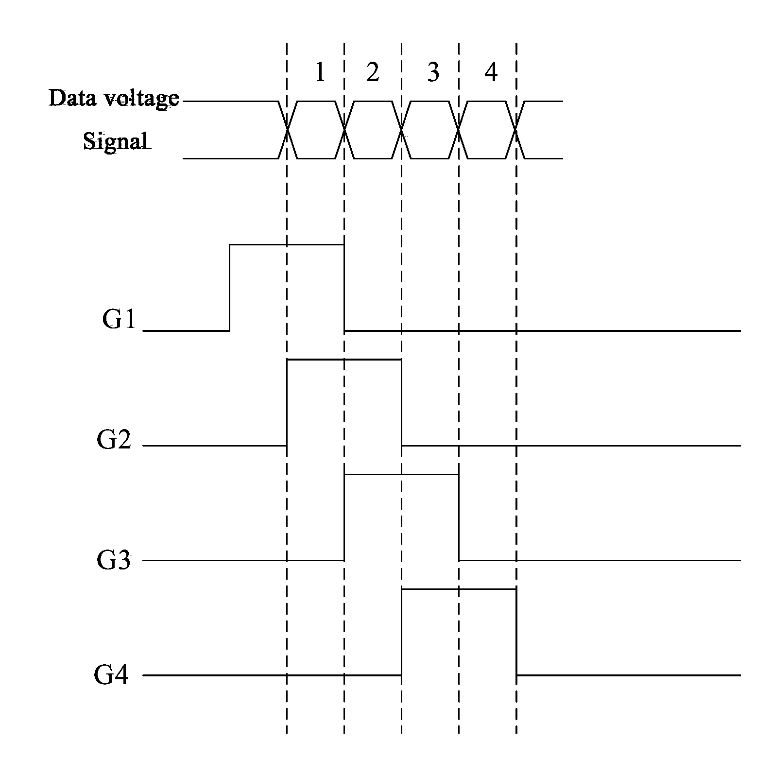
[0050]Embodiments of the present invention provides a display driving method which can reduce the coupling phenomenon due to rapid changes in voltage on the gate lines, improving the stability of display.

[0051]In the following description, for illustration rather than limitation, specific details such as system structures, interfaces, techniques are proposed for a thorough understanding of the present invention. However, other embodiments of the present invention without these specific details are apparent to those skilled in the art. In other instances, detailed description to the well-known devices, circuits, and methods is omitted in order to avoid unnecessary detail description from dimming the prevent invention.

[0052]The display driving method according to the present invention can be used for driving a display device, wherein the display device may include: a liquid crystal display or an organic light emitting diode (OLED) panel. Various embodiments of the present invention ar...


PUM


Abstract

The embodiment of the present invention provides a display driving method which can reduce the coupling effect due to the rapid changes of the voltage on the gate line and improve stability of display. The display driving method uses an overlapping scan mode, wherein every two rows of pixel units have two gate lines, the two gate lines drive the pixel units connected thereto respectively, each gate line group including N pairs of adjacent two gate lines, N being a natural number, said driving method comprising: providing a switching voltage signal to the odd gate lines in the gate line group sequentially; and providing a switching voltage signal to the even gate lines in the gate line group sequentially; wherein when the switching voltage signal on the odd gate lines is in the falling edge, the switching voltage signal on the even gate lines is in the rising edge.

Description

FIELD OF THE INVENTION[0001]The present invention relates to the field of display, particularly to a display driving method.BACKGROUND OF THE INVENTION[0002]With the continuous development of electronic technology, LCD displays have been widely used in various fields. A thin film transistor (TFT) array substrate is an important part of a liquid crystal display. Most TFT array substrate includes a base, common electrode lines, gate lines and data lines and other structures, wherein the gate lines are disposed between the two rows of sub-pixels, the data lines are disposed between the two columns of sub-pixels, the crossing regions of the gate lines and the data lines form the pixel units; the common electrode lines are also disposed between two rows of sub-pixels.[0003]A driving method shown in FIG. 1 uses the overlapping scan driving modes, that is the gate pulse signal are overlapped therebetween. FIG. 1 shows the data voltage signal on the data lines and the switching voltage sign...

Claims


Application Information

Patent Timeline
Patent Type & Authority Applications(United States)
IPC IPC(8): G09G3/36
CPCG09G3/3648G09G2310/0205G09G3/3677G09G3/20G09G3/36G09G2310/0224G09G2310/08G09G2320/0219
Inventor LIU, RUIZHANG, HAODONG, XUEKIM, HYUNGKYUXIE, XIAOBO
Owner BEIJING BOE OPTOELECTRONCIS TECH CO LTD
Why Eureka
Try Eureka