Power supply

Active Publication Date: 2014-06-26
SOLUM CO LTD +1
View PDF16 Cites 5 Cited by
  • Summary
  • Abstract
  • Description
  • Claims
  • Application Information

AI Technical Summary

Benefits of technology

The patent describes a power supply that improves efficiency. It includes a main converter that converts chemical energy into electrical energy, and a smaller converter that reduces output loss. The smaller converter is controlled based on a "hold-up time," which means it adjusts its output to match the needs of the load. This design helps to increase the amount of energy that is available for use by the load.

Problems solved by technology

Therefore, the PSFB has the problem in that efficiency in supplying power is lowered.

Method used


Image

  • Power supply
  • Power supply
  • Power supply

Examples


Embodiment Construction

[0028]Embodiments of the present invention will now be described in detail with reference to the accompanying drawings. The embodiments of the present invention may be modified in many different forms and the scope of the invention should not be limited to the embodiments set forth herein. Rather, these embodiments are set forth to provide thorough and complete understanding of the present invention, and will fully convey the concept of the invention to those skilled in the art. In the accompanying drawings, shapes and dimensions of elements may be exaggerated for clarity.

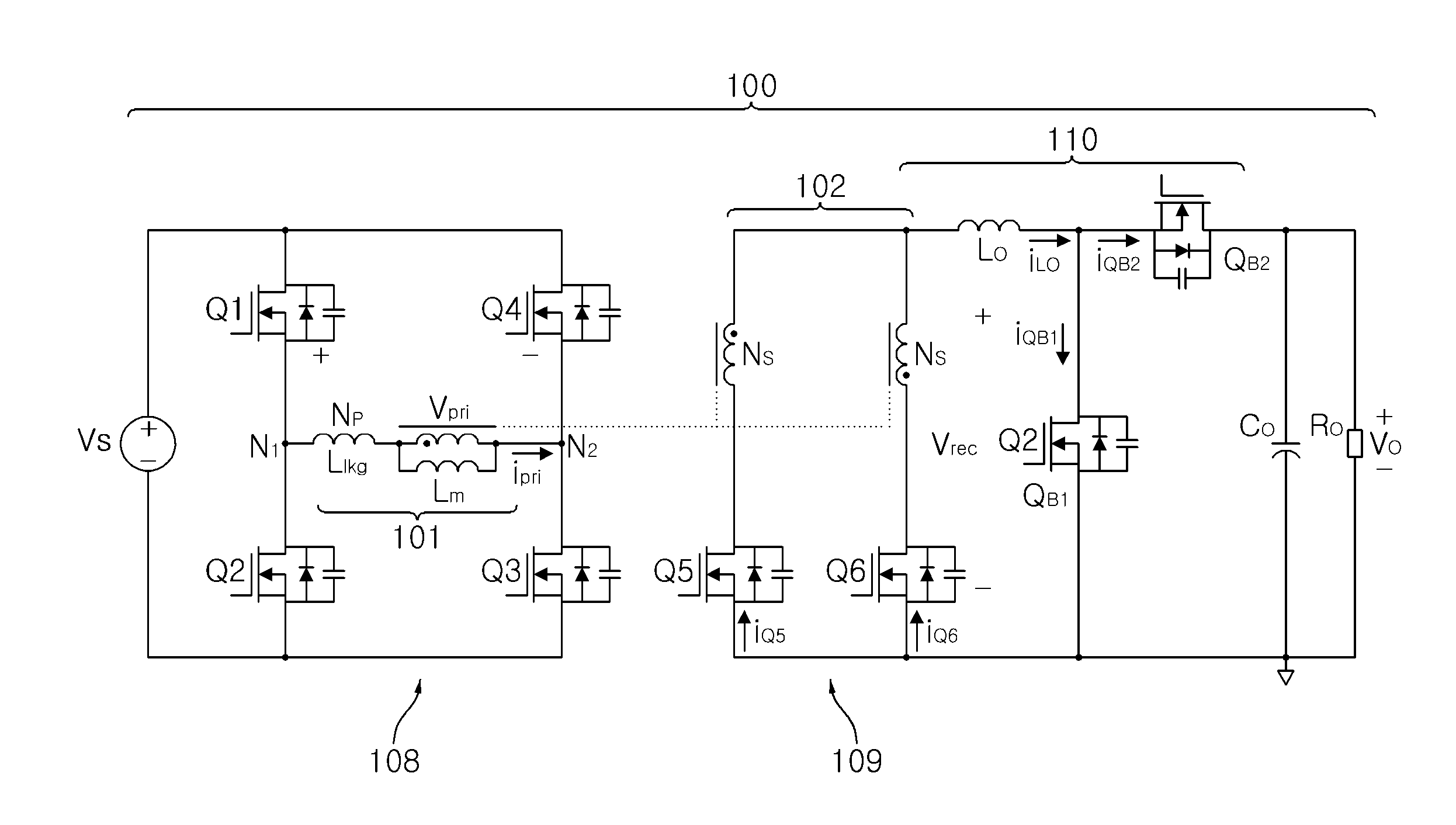
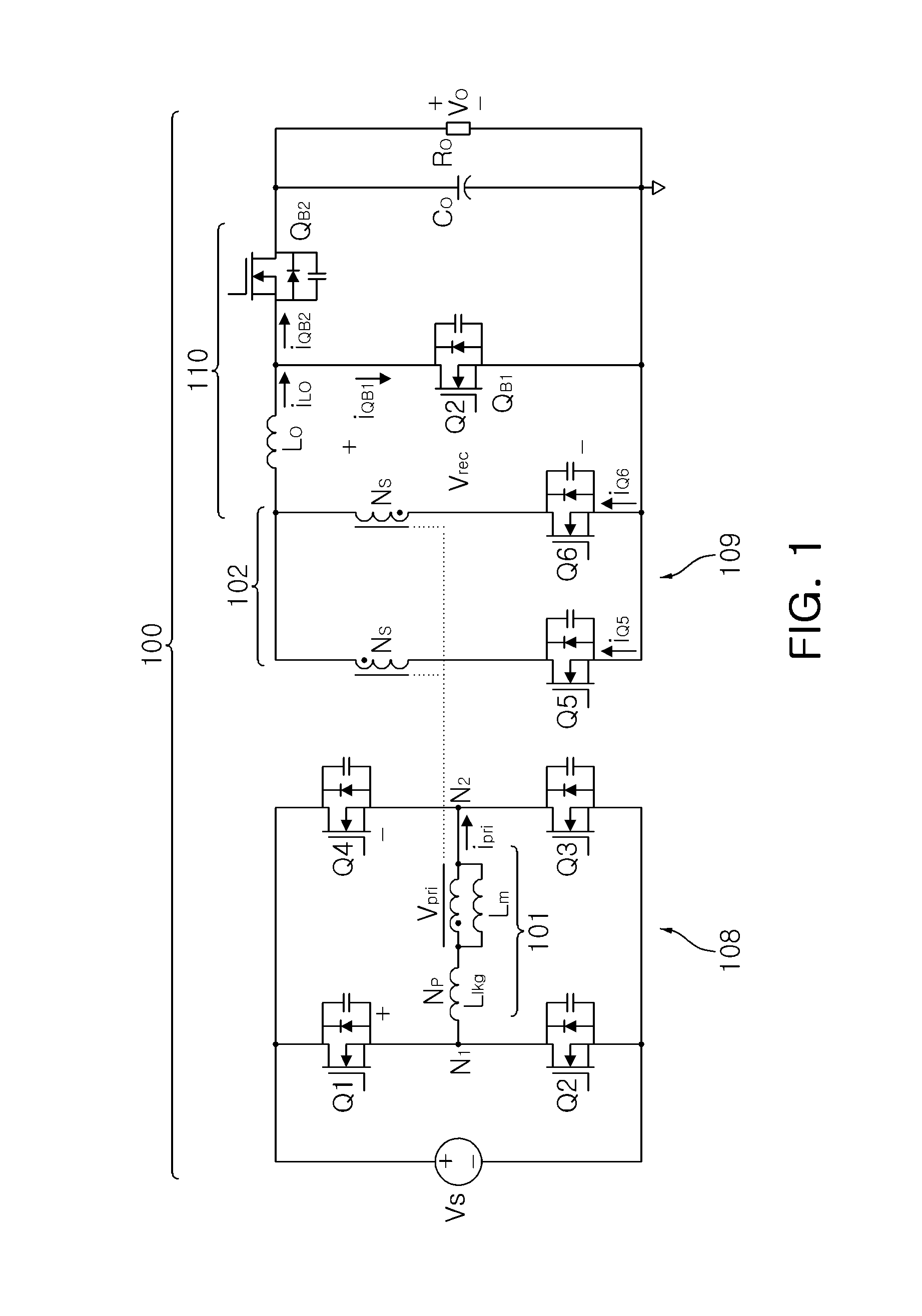
[0029]FIG. 1 is a circuit diagram of a power converter according to one embodiment of the present invention.

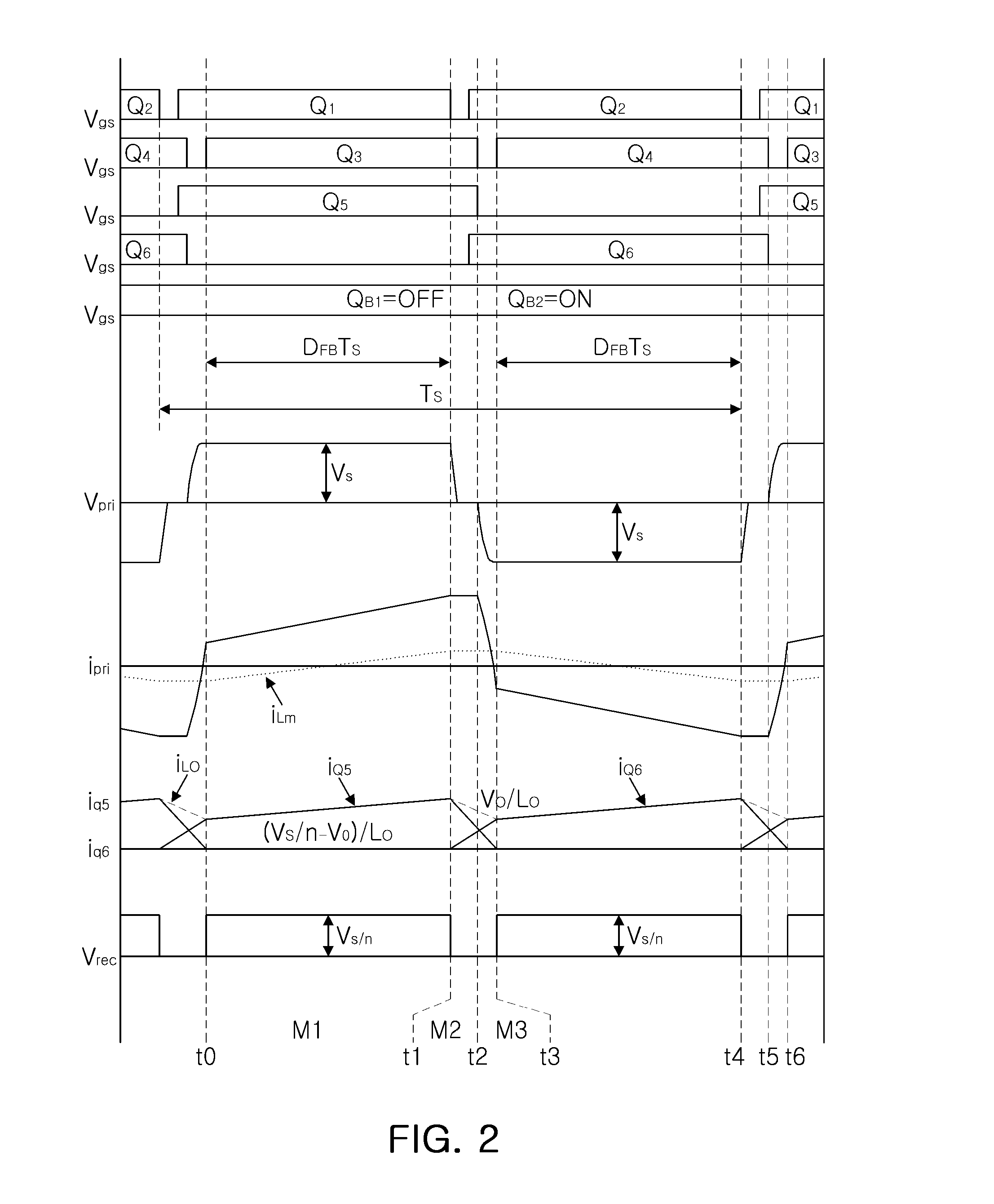
[0030]FIGS. 2 and 3 are diagrams showing waveforms of main elements of a power converter according to an embodiment of the present invention.

[0031]A power converter according to an embodiment of the present invention may include a main converter 100 supplying main power to a load, and a sub converter 110 redu...


PUM


Abstract

There is provided a power supply including a direct current (DC) to DC converter supplying main power to a load, and a sub converter connected to the DC to DC converter and reducing output loss, wherein the sub converter is operable based on a hold-up time.

Description

CROSS-REFERENCE TO RELATED APPLICATIONS[0001]This application claims the priority of Korean Patent Application No. 10-2012-0151302 filed on Dec. 21, 2012, in the Korean Intellectual Property Office, the disclosure of which is incorporated herein by reference.BACKGROUND OF THE INVENTION[0002]1. Field of the Invention[0003]The present invention relates to a power supply operable during a hold-up time and thus capable of reducing output loss.[0004]2. Description of the Related Art[0005]In general, a phase shifted full bridge (PSFB) converter is widely used as a direct current (DC) to DC converter in a power supply. This is due to the fact that such a PSFB converter places less stress on a semiconductor device and allows zero voltage switching, and is thus suitable for high capacity applications.[0006]The DC to DC converter needs to meet hold-up time requirements. That is, since a load is to be powered for a certain period of time, even if an input alternating current power supply is in...

Claims


Application Information

Patent Timeline
IPC IPC(8): H02M3/335H02M1/00
CPCH02M3/33507H02M3/33576H02M1/0058H02M1/007H02M1/0096Y02B70/10H02M3/155
Inventor KIM, JAE KOOKKIM, CHONG EUNKIM, SUNG HORYU, DONG KYUN
Owner SOLUM CO LTD
Why Eureka
Try Eureka