Magnetic Field Antenna

a magnetic field antenna and wireless communication technology, applied in the direction of loop antennas, loop antennas with ferromagnetic cores, electrical transducers, etc., can solve the problems of large ear plugs, unfavorable headset earcups, and large communication ear plugs

Active Publication Date: 2014-06-26
RED TAIL HAWK CORP
View PDF3 Cites 62 Cited by
  • Summary
  • Abstract
  • Description
  • Claims
  • Application Information

AI Technical Summary

Benefits of technology

[0014]In accordance with a preferred embodiment of the invention, at least a portion of the antenna body of the MFA is used as a continuation of the magnetic core for an antenna coil, thus directing a greater number of magnetic field lines through the antenna coil. In a preferred embodiment, the antenna body of the MFA also provides a magnetic shunt around at least one electrical component electrically coupled to the antenna coil to provide at least partial magnetic shielding of the electrical component.

Problems solved by technology

Large communications earplugs tend to be uncomfortable because they put pressure on the ear.
Moreover, a large earplug may interfere with a headset earcup when the earplug and headset are worn together to provide “double hearing protection”.
Electromagnetic waves impinging on electrical components can produce undesired voltages and currents that cause undesired effects.
It is undesirable for the electrical components used within the antenna to generate voltages from external fields in an unpredictable way.
In particular, electret microphones are sensitive to electromagnetic fields, and this is a known problem in the art.

Method used


Image

  • Magnetic Field Antenna
  • Magnetic Field Antenna
  • Magnetic Field Antenna

Examples


Embodiment Construction

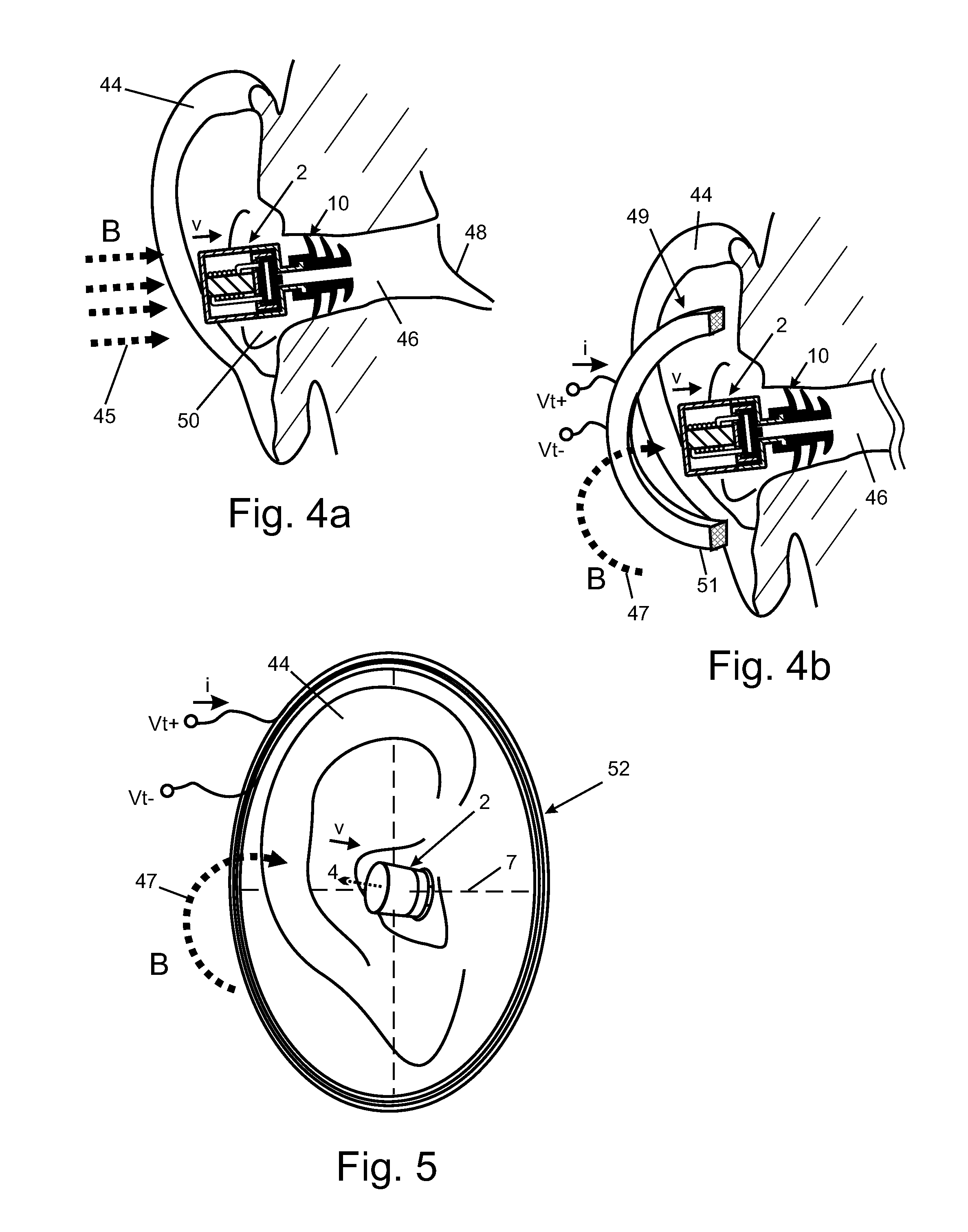
[0044]It should be noted here that for explanatory purposes the figures herein include indications of unperturbed field lines, redirected magnetic field lines and optimal orientations of the MFA relative to the field. The field lines and orientations are provided for illustrative purposes and should not be taken to be exact representations of optimal orientations and magnetic field line paths.

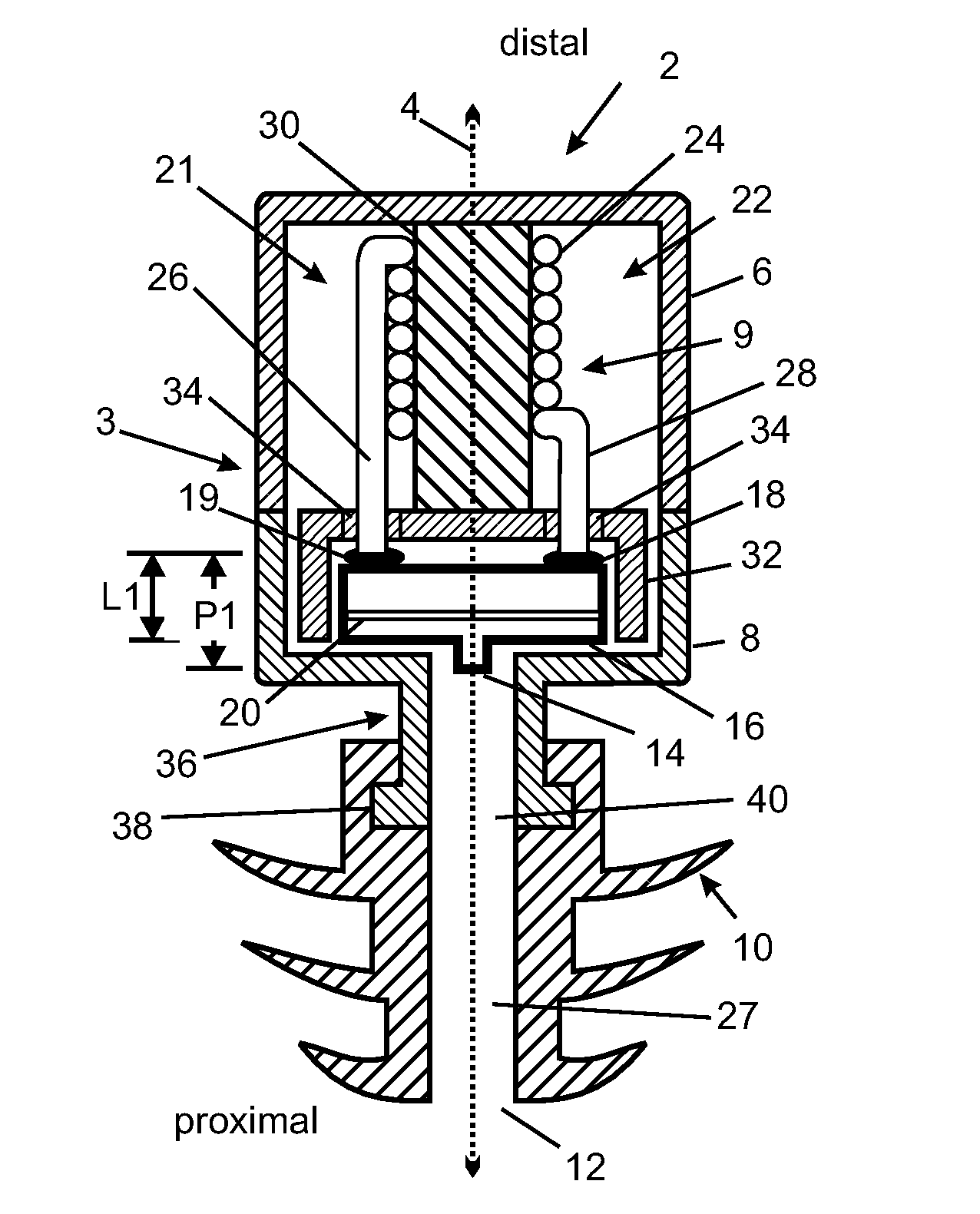
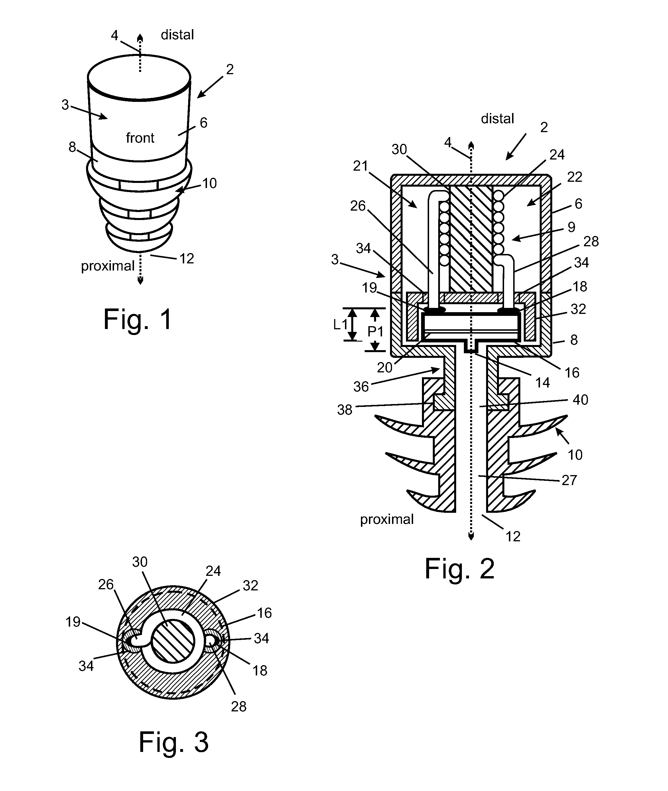
[0045]FIG. 1 shows a three-dimensional drawing of an embodiment of the invention: a battery-free wireless communications earplug 2. The exterior geometry of the communications earplug 2 embodiment of the invention is symmetric about an earplug axis 4. The proximal end of the communications earplug 2 is the end that is closest to the eardrum when the communications earplug 2 is properly inserted in an ear. The distal end is the end farthest from the eardrum. This embodiment of the invention incorporates an outer surface 3 comprising a cover 6 and base 8.

[0046]This embodiment is sized to fit in a...


PUM


Abstract

A magnetic field antenna that provides high efficiency and a compact form factor. Electromagnetic shielding of electrical components used in the antenna is provided, and one embodiment of the invention is a wireless battery-free communications earplug.

Description

REFERENCE TO RELATED APPLICATIONS[0001]This application is a continuation-in-part of co-pending U.S. application Ser. No. 12 / 832,363, published as publication number US 2010 / 0296667, entitled “Wireless Earplug with Improved Sensitivity and Form Factor”, filed Jul. 8, 2010, which claimed the benefit of Provisional Application No. 61 / 224,531, filed Jul. 10, 2009, entitled “Wireless Earplug with Improved Sensitivity and Form Factor”, and was a continuation-in-part of U.S. application Ser. No. 11 / 837,129, published as publication number US 2009 / 0041285, entitled “Wireless Communications Headset System Employing a Loop Transmitter That Fits Around the Pinna”, filed Aug. 10, 2007, which claimed the benefit of Provisional Application No. 60 / 824,091, filed Aug. 31, 2006, entitled “Wireless Communications System Employing a Loop Transmitter That Fits Around The Pinna”. The aforementioned applications are hereby incorporated herein by reference.BACKGROUND OF THE INVENTION[0002]1. Field of the...

Claims


Application Information

Patent Timeline
Patent Type & Authority Applications(United States)
IPC IPC(8): H04R1/10H01Q7/08H01Q1/27
CPCH04R1/1091A61F11/08H01Q1/273H01Q7/08H04M1/05
Inventor PARKINS, JOHN W.
Owner RED TAIL HAWK CORP
Why Eureka
Try Eureka