Poultry loader with alignment mechanism

a technology of rams and loaders, which is applied in the direction of packaging foodstuffs, transportation and packaging, and packaged goods types, etc. it can solve the problems of delayed production line, unfavorable production line, and uneven placement of chickens in front of rams

Active Publication Date: 2014-07-03
PRETSITEK KORP
View PDF15 Cites 4 Cited by
  • Summary
  • Abstract
  • Description
  • Claims
  • Application Information

AI Technical Summary

Benefits of technology

[0006]An improved loader has an adjustable alignment mechanism to keep material in alignment as it is loaded into a bag. The loader includes a frame having an upper surface, a pair of horns adjustably connected to the upper surface, each horn comprising an upper shoulder, a lower shoulder, and an air duct between the upper shoulder and the lower shoulder, a pair of air hoses connecting each air duct to a controller, the controller being connected to a pressurized air supply, and an alignment mechanism mounted to the frame, the alignment mechanism including an axle, a first arm connected to a first panel, a second arm connected to a second panel, the second arm rotatably connected to the first arm at the axle, a gear mechanism connected to the axle, the first arm, and the second arm, the gear mechanism configured to rotate the second arm in a direction opposite to a direction of rotation of the first arm, and a dual-action cylinder connected to at least one of the first arm and the second arm.

Problems solved by technology

Chickens being bagged in this manner are not uniform in shape or size.
The placement of chickens in front of the ram is not necessarily uniform.
If the chicken veers to one side as it is pushed into the bag, it might tear the bag, or it might not proceed entirely into the bag, leaving, for example, a leg sticking out of the bag, any of which situations cause a delay on the production line.
Additionally, the chicken could turn sideways, and even if it is bagged, clipped, and sealed, the improper orientation will likely cause problems in transport and in marketing of the chicken.

Method used


Image

  • Poultry loader with alignment mechanism
  • Poultry loader with alignment mechanism
  • Poultry loader with alignment mechanism

Examples


Embodiment Construction

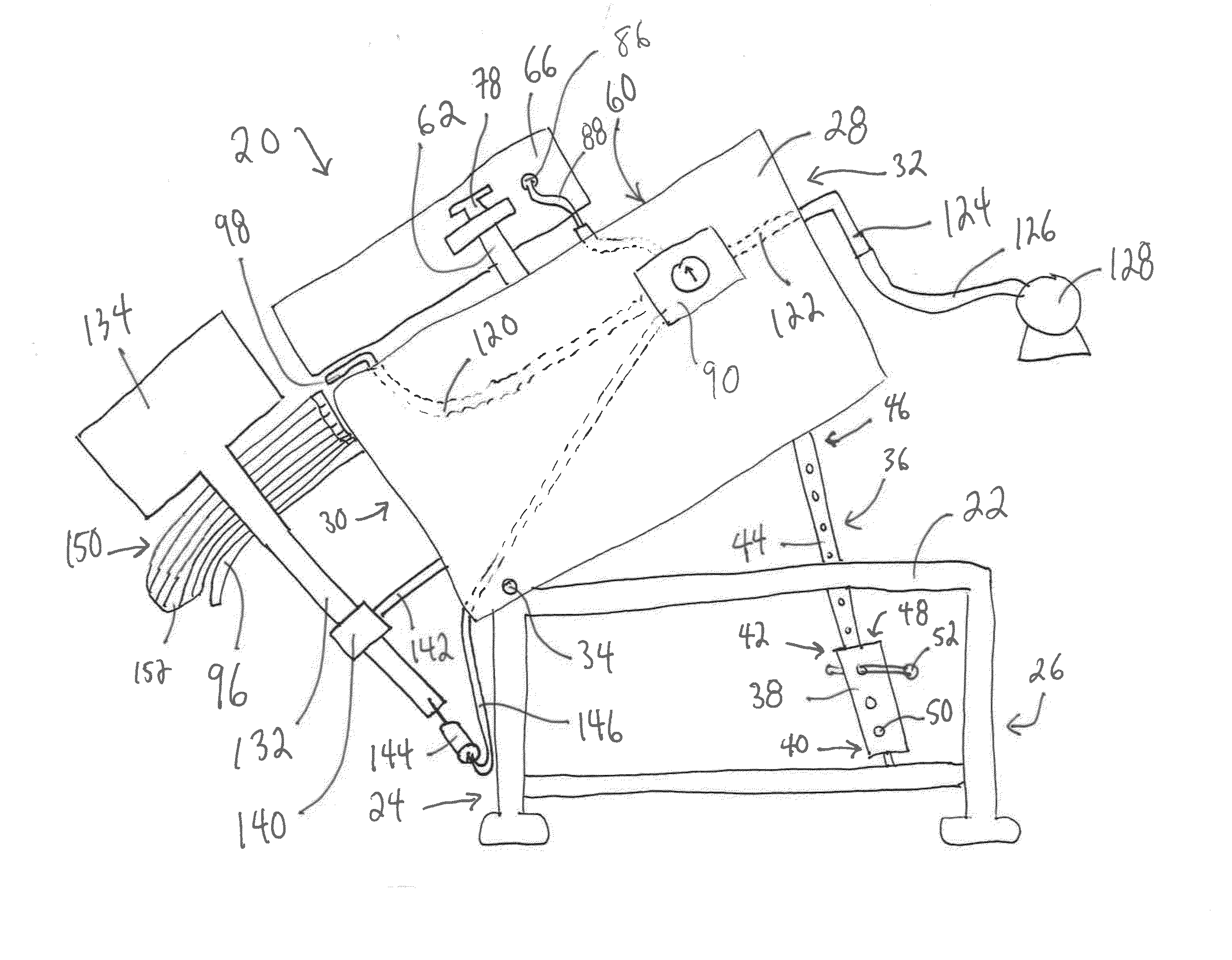
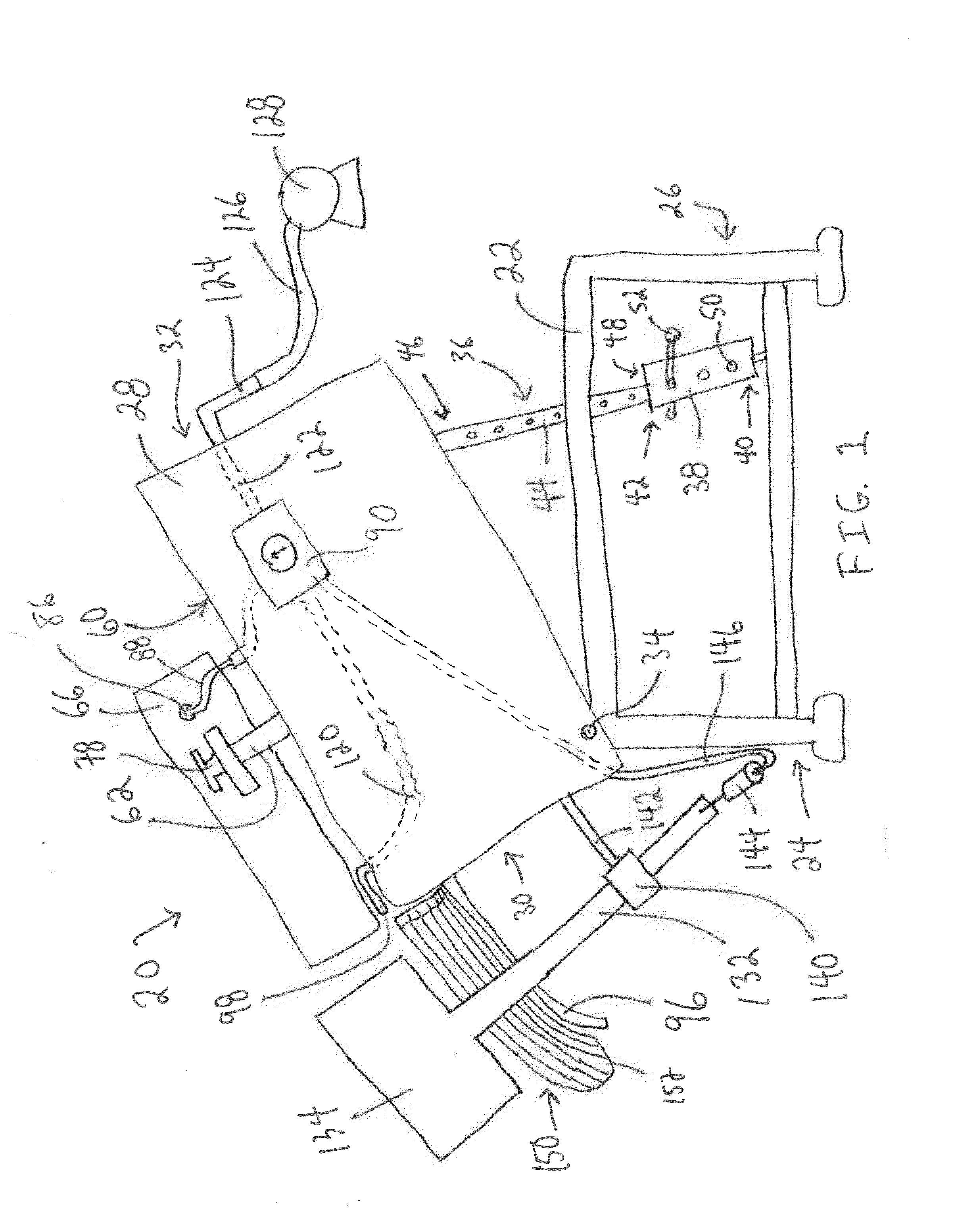
[0020]While the invention may be susceptible to embodiment in different forms, there is shown in the drawings, and herein will be described in detail, specific embodiments with the understanding that the present disclosure is to be considered an exemplification of the principles of the invention, and is not intended to limit the invention to that as illustrated and described herein. The embodiments of the present invention will be described as part of an automated poultry loader. The present invention, however, can also be used for loading any other materials in which proper alignment of the material is necessary or desired.

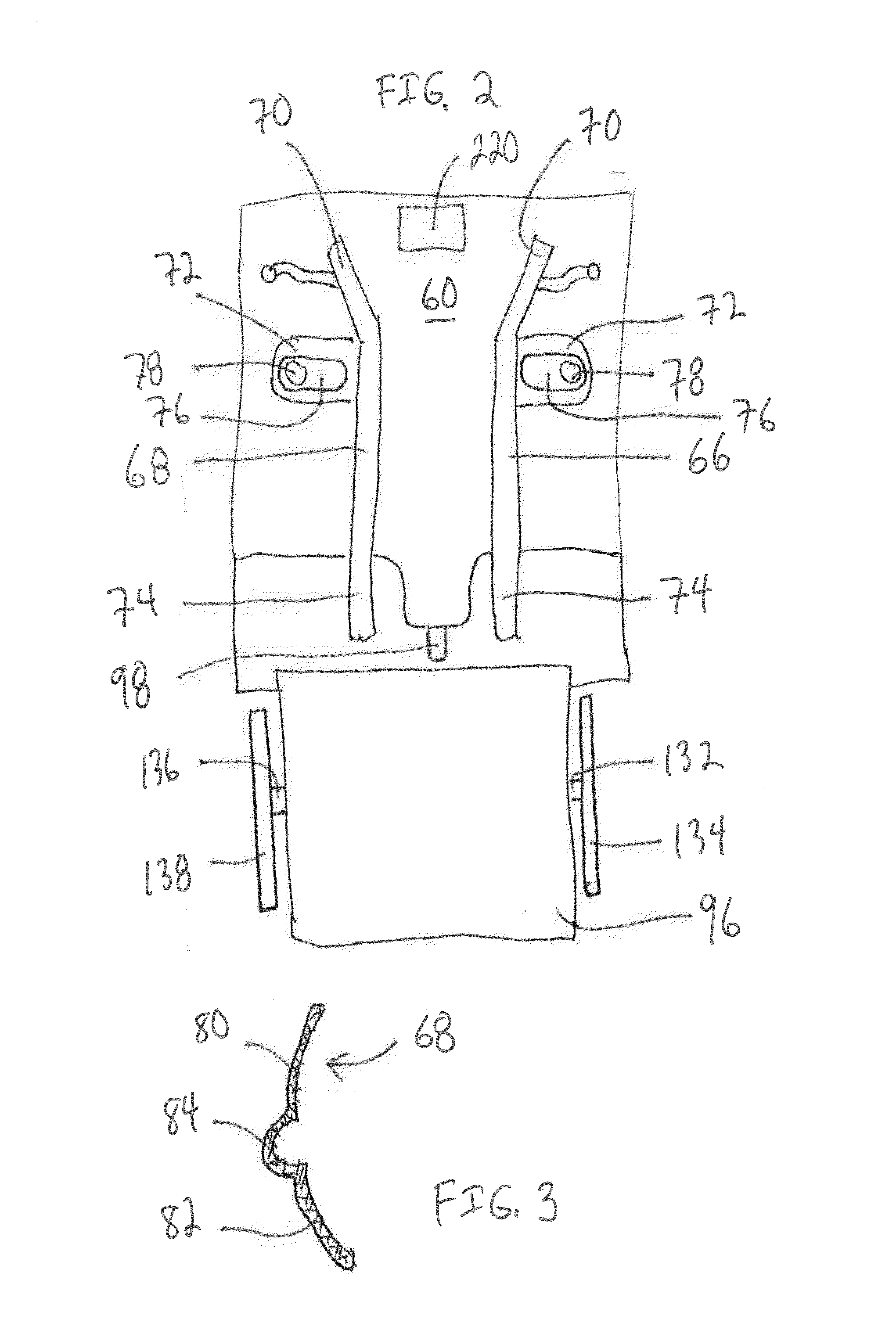
[0021]A poultry loader 20 of the preferred embodiment of the present invention is shown in elevation schematic view in FIG. 1 and in top plan view in FIG. 2. Loader 20 has a lower frame 22 with a first end 24 and a second end 26, and an upper frame 28 with a first end 30 and a second end 32. Lower frame first end 24 connects to upper frame first end 30 at rotatin...


PUM


Abstract

An improved loader is described. The loader includes a frame having an upper surface, a pair of horns adjustably connected to the upper surface, each horn comprising an upper shoulder, a lower shoulder, and an air duct between the upper shoulder and the lower shoulder, a pair of air hoses connecting each air duet to a controller, the controller being connected to a pressurized air supply, and an alignment mechanism mounted, the alignment mechanism including an axle mounted to the frame, a first arm connected to a first panel, the first arm rotatably connected to the axle, a second arm connected to a second panel, the second arm rotatably connected to the axle, a gear mechanism connected to the axle and to the first arm and the second arm, the gear mechanism configured to rotate the second arm in a direction opposite to a direction of rotation of the first arm, and a dual-action cylinder connected to at least one of the first arm and the second arm.

Description

PRIORITY[0001]This application claims priority from U.S. Provisional Patent Application No. 61 / 624,720, filed Apr. 16, 2012, the disclosure of which is incorporated herein in its entirety.FIELD OF THE INVENTION[0002]The present invention relates generally to devices for loading material into bags. The invention relates more specifically to devices for loading whole dressed poultry into plastic bags.BACKGROUND OF THE INVENTION[0003]Automated loaders are commonly used to place material in packaging for storage, transport, or sale. For example, in a conventional poultry loader, a plastic bag is opened, sometimes by air and sometimes by mechanical means, such as a pair of horns. A whole dressed chicken is then pushed into the bag, sometimes manually, sometimes by gravity, sometimes by a ram. The bagged chicken is then sealed within the bag. Conventionally, the bag is clipped and the tail is severed. In some cases, prior to clipping, the air in the bag is evacuated. In other cases, the b...

Claims


Application Information

Patent Timeline
Patent Type & Authority Applications(United States)
IPC IPC(8): B65B43/42
CPCB65B1/04B65B5/00B65B5/045B65B17/00B65B25/064B65B43/36B65B43/42B65B51/043B65B65/00
Inventor HASCHKE, EGGOZURWIEDEN, MARTIN
Owner PRETSITEK KORP
Why Eureka
Try Eureka