
Automatic sampler

Active Publication Date: 2014-07-03
SHIMADZU CORP
View PDF0 Cites 13 Cited by
  • Summary
  • Abstract
  • Description
  • Claims
  • Application Information

AI Technical Summary

Benefits of technology

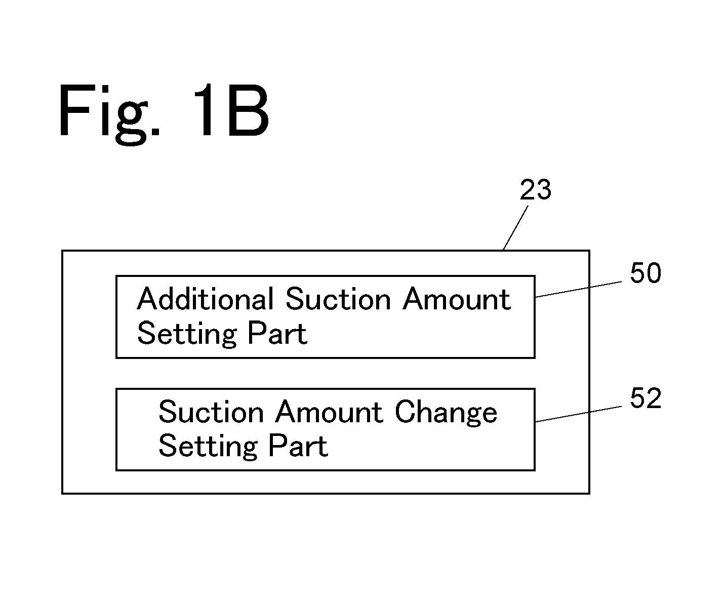
The present invention aims to provide a device for confirming the amount of sample actually sucked from a sample container. The invention includes a sample suction amount setting part that can automatically adjust the sample suction amount to match the predetermined amount set in the sample suction amount setting part. This ensures that the sample can be accurately injected into the analyzing device, without the need for the analyzer to calibrate the analysis result based on the actual sample suction amount. The invention also includes a suction amount change setting part that can adjust the suction amount to match the amount of sample in the sample container, preventing air from being trapped in the pump or passage on the analyzing device. Furthermore, the invention includes a weight sensor fixed to the sample container placing portion, which automatically calculates the amount of sample actually sucked from the sample container based on a change in measurement value by the weight sensor before and after the sample suction. This eliminates the need for manual measurement of the sample suction amount, making it easier to verify whether or not the sample suction mechanism is operating normally.

Problems solved by technology

However, with this system, the sample spilling from the sample loop is discharged to a drain, and therefore, the sample is largely consumed.
Therefore, a suction error made by the metering pump signifies an error of the injection amount as it is, thereby affecting the reproducibility of the amount of sample to be injected to the analyzing device.
In the case where deficient suction occurs in the metering pump or the amount of sample in the sample container is insufficient in the automatic sampler, the amount of sample to be injected to the analyzing device is smaller than the predetermined amount, thereby possibly affecting an analysis result.
This problem is more conspicuous in the loop injection system.
Only the amount of sample less than or equal to the volume of the sample loop can be possibly suctioned due to deficient suction by the metering pump also in the total amount injection system, thereby raising a problem.
However, this verification requires the manual work of the analyzer, thereby raising the problems of an increase in time and labor, and further, occurrence of artificial errors.

Method used


Image

  • Automatic sampler
  • Automatic sampler
  • Automatic sampler

Examples


Embodiment Construction

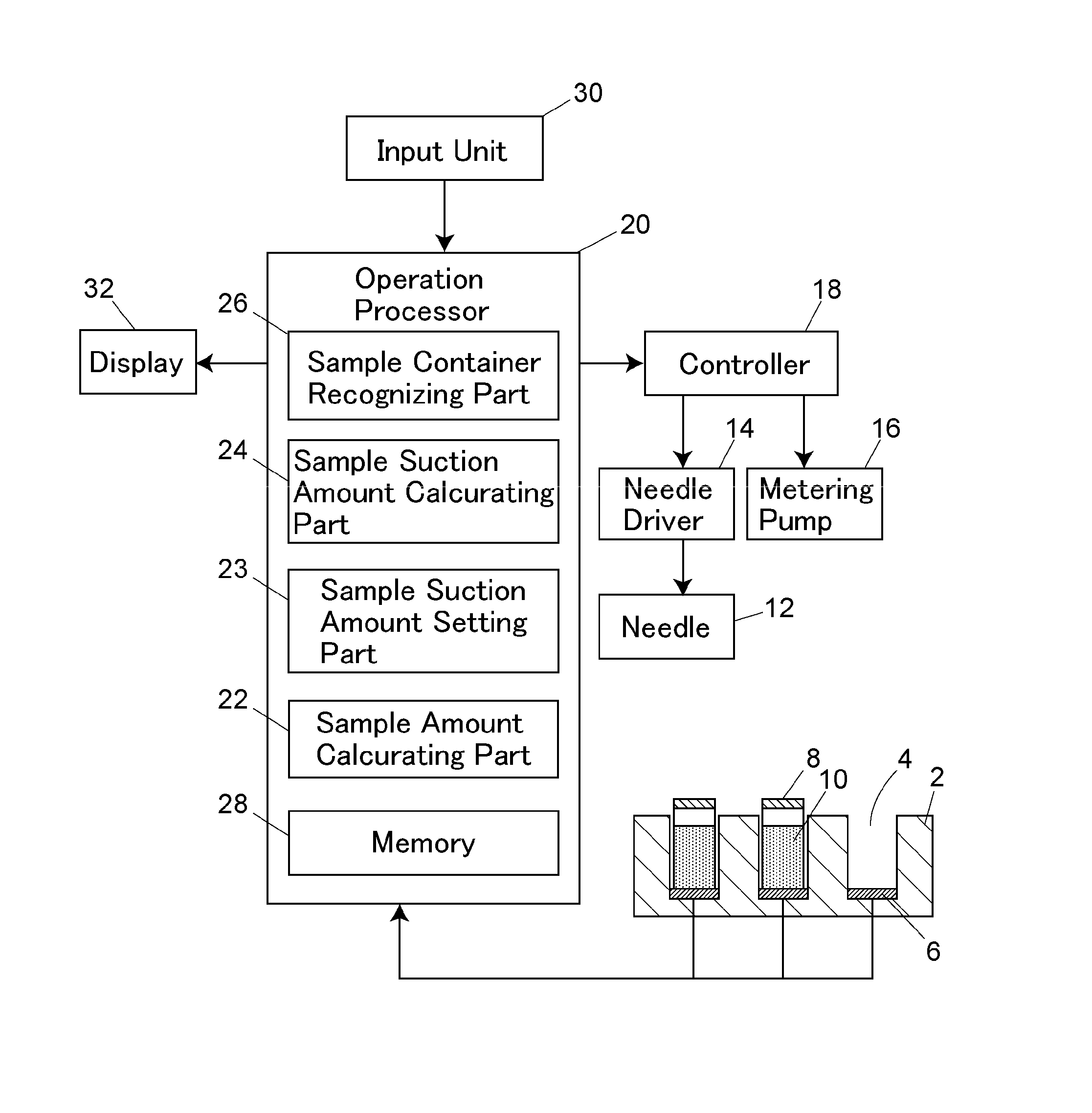
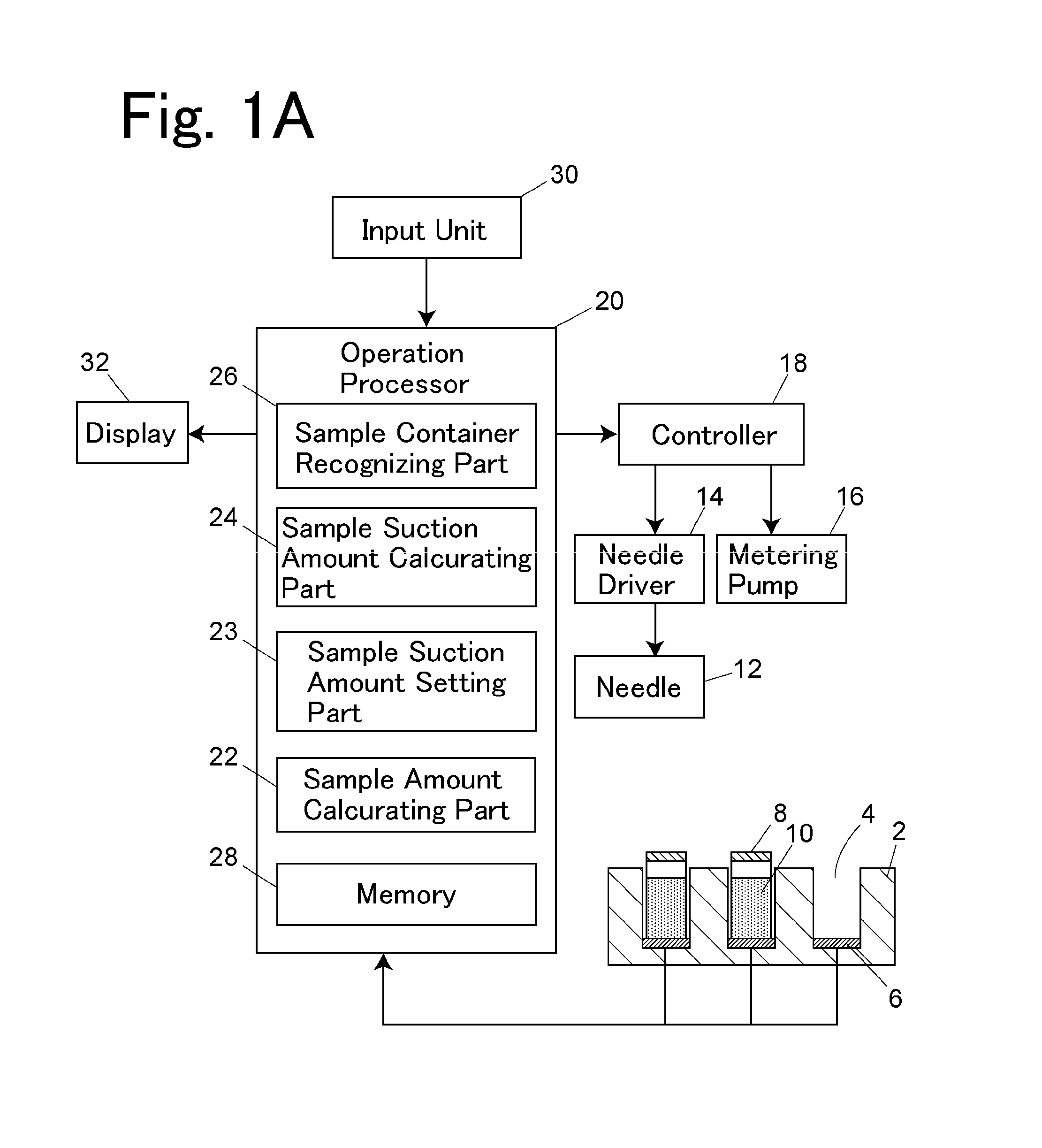
[0024]One example of an automatic sampler will be described with reference to FIG. 1.

[0025]A rack 2 is provided for containing sample containers 8 therein, and further, has a plurality of sample container placing portions 4, in each of which the sample container 8 is placed. A weight sensor 6 is placed at the bottom of each of the sample container placing portions 4. The weight sensor 6 is, for example, a piezoelectric transducer (i.e., piezo element) or a pressure sensor element that can measure the weight of the placed sample container 8.

[0026]A sample suctioning mechanism for suctioning a sample from the sample container 8 comprises a needle 12, a needle driver 14, and a metering pump 16. The needle driver 14 is adapted to drive the needle 12 inward on a horizontal plane and in a vertical direction. The needle 12 is moved to the sample container 8 containing therein a sample 10 to be suctioned by the needle driver 14, and then, its tip is inserted into the sample contained inside...


PUM


Abstract

A weight sensor for measuring the weight of a sample container is fixed to a sample container placing portion. The amount of sample contained in the sample container placed in the sample container placing portion is determined based on a measurement value by the weight sensor. A change in amount of sample contained in the sample container is determined before and after sample suction by a sample suction mechanism. The amount of sample actually suctioned from the sample container is determined based on the change.

Description

BACKGROUND OF THE INVENTION[0001]1. Field of the Invention[0002]The present invention relates to an automatic sample injecting apparatus (hereinafter referred to as an “automatic sampler”) for suctioning a sample from a sample container containing the sample so as to inject the suctioned sample to an analyzing device such as a liquid chromatograph.[0003]2. Description of the Related Art[0004]An automatic sampler is generally provided with a needle for suctioning and ejecting a sample, a mechanism for moving the needle, a metering pump, and a valve for switching connection between a plurality of passages (see, for example, Unexamined Patent Application Publication No. 2005-265805).[0005]There are two systems for an automatic sampler: a total amount injection system and a loop injection system. In an automatic sampler of a total amount injection system, a sample loop is connected between a needle and a metering pump via a valve, to then be filled with a sample suctioned in a larger am...

Claims


Application Information

Patent Timeline
IPC IPC(8): G01N1/14
CPCG01N1/14G01N35/1016G01N2035/00217
Inventor OKOBA, TSUTOMU
Owner SHIMADZU CORP
Learn More