Supercharge Your Innovation With Domain-Expert AI Agents!

Heat exchanger manifold with a fluid flow distribution feature

a technology of fluid flow and heat exchanger, which is applied in the field of heat exchanger, can solve the problems of poor heat exchange efficiency, difficulty in introducing hot radiator liquid into the tubular elements, and lack of us

Inactive Publication Date: 2014-07-03
HANON SYST
View PDF4 Cites 2 Cited by
  • Summary
  • Abstract
  • Description
  • Claims
  • Application Information

AI Technical Summary

Benefits of technology

The present disclosure describes a radiator that can evenly release a liquid. The invention also includes a heat exchanger with a manifold that gradually decreases in size and a conditioning assembly with tubular elements that have a fluid flow distribution feature integrally formed therein. Additionally, a method of making the heat exchanger is also included. The technical effects of the invention include efficient heating and cooling, reduced size and complexity, and improved fluid flow distribution.

Problems solved by technology

One drawback of such conventional radiators is poor heat exchange efficiency, especially during cold start-up transients.
The back wall directs the radiator liquid downward, causing the tubular elements adjacent the inlet to receive the hot radiator liquid which leads to difficultly in introduction of the hot radiator liquid into the tubular elements adjacent an opposite end of the first manifold, especially during the cold start up.
Such non-uniform distribution of the hot radiator liquid can cause the tubular elements adjacent the opposite end of the first manifold to become obstructed by an accumulation of the radiator liquid therein resulting from a lack of use.
As a result, severe thermal stresses which can potentially damage the tubular elements adjacent the opposite end of the first manifold may occur.

Method used


Image

  • Heat exchanger manifold with a fluid flow distribution feature
  • Heat exchanger manifold with a fluid flow distribution feature
  • Heat exchanger manifold with a fluid flow distribution feature

Examples


Embodiment Construction

[0018]The following detailed description and appended drawings describe and illustrate various exemplary embodiments of the invention. The description and drawings serve to enable one skilled in the art to make and use the invention, and are not intended to limit the scope of the invention in any manner.

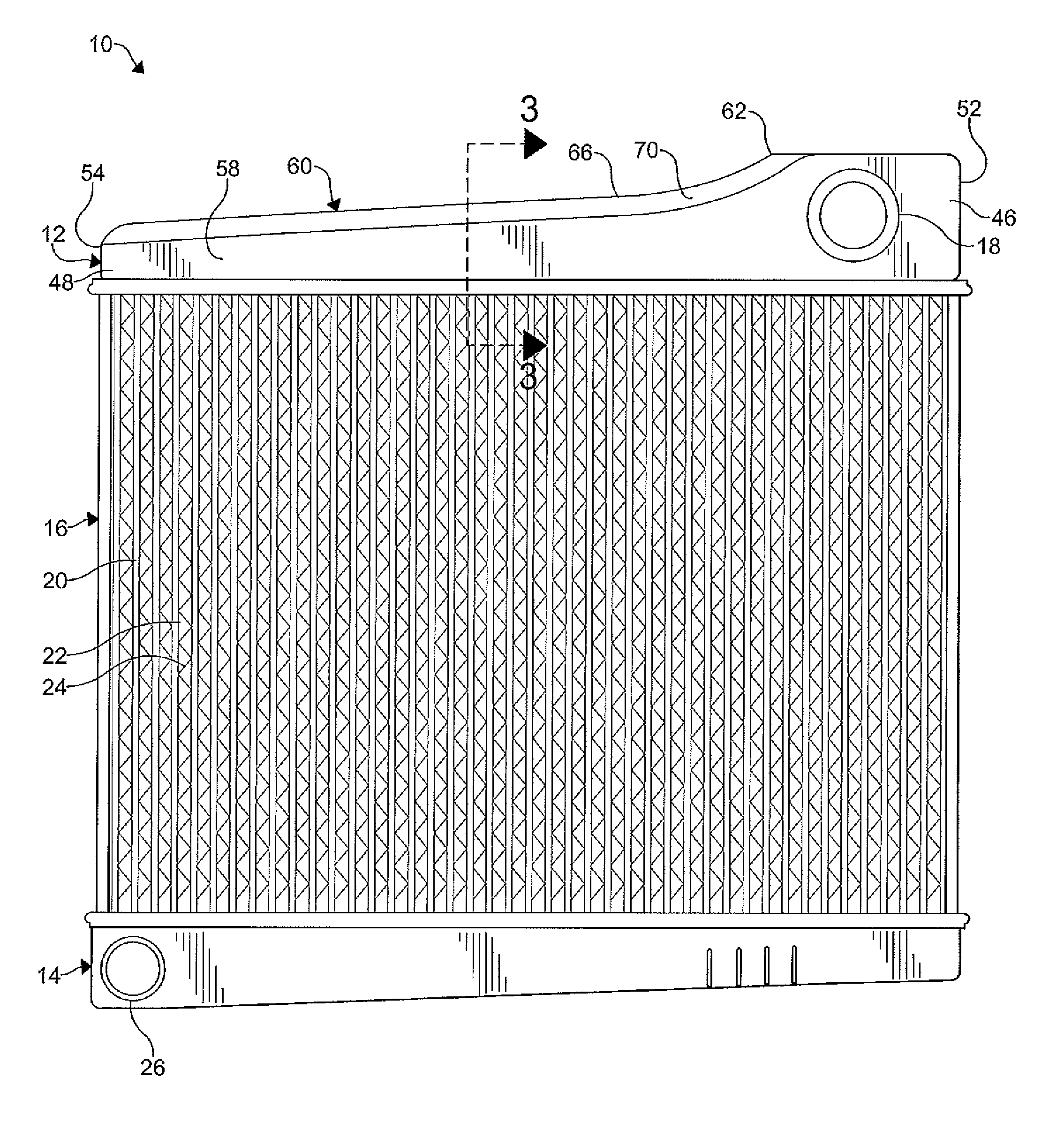
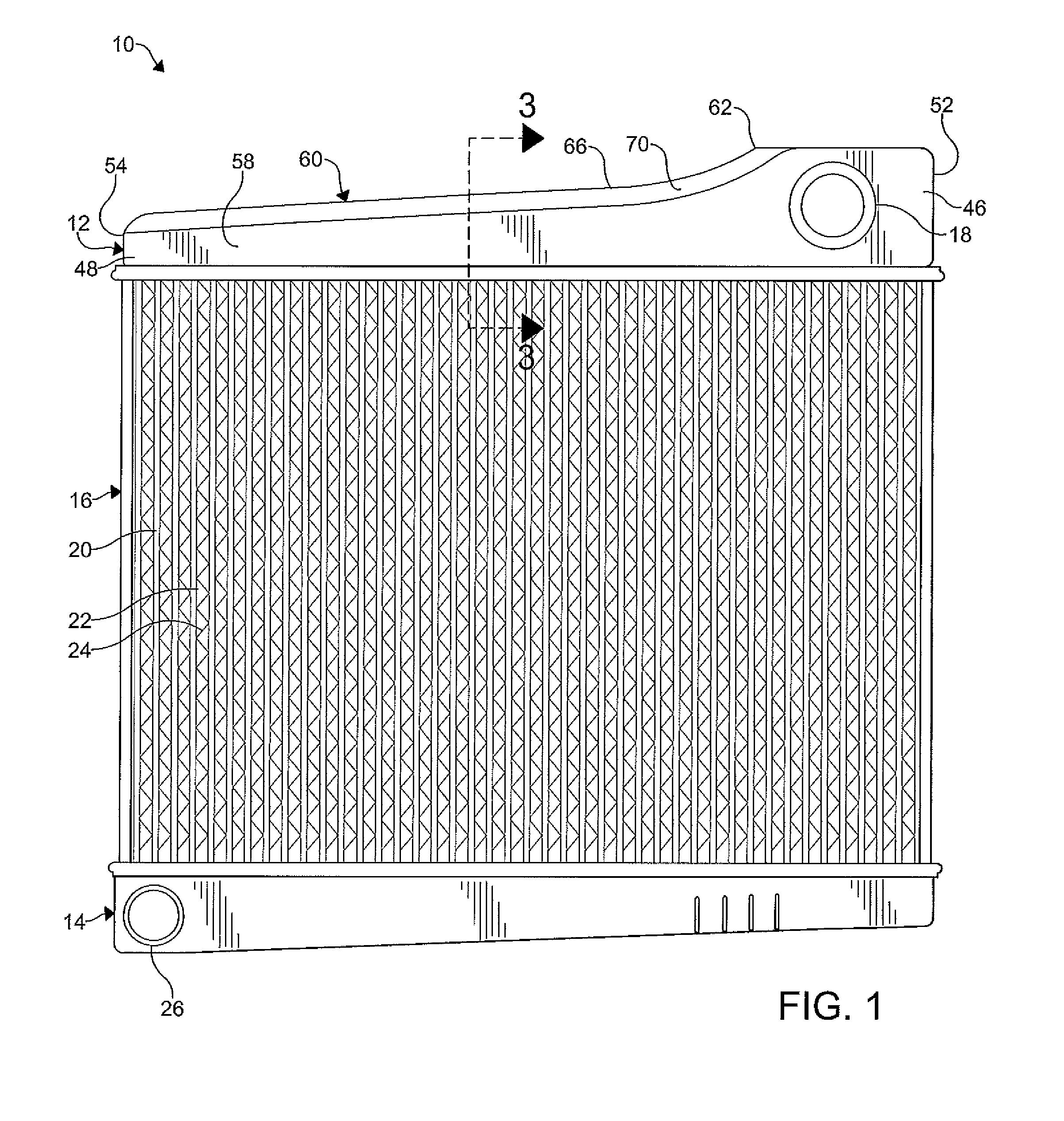
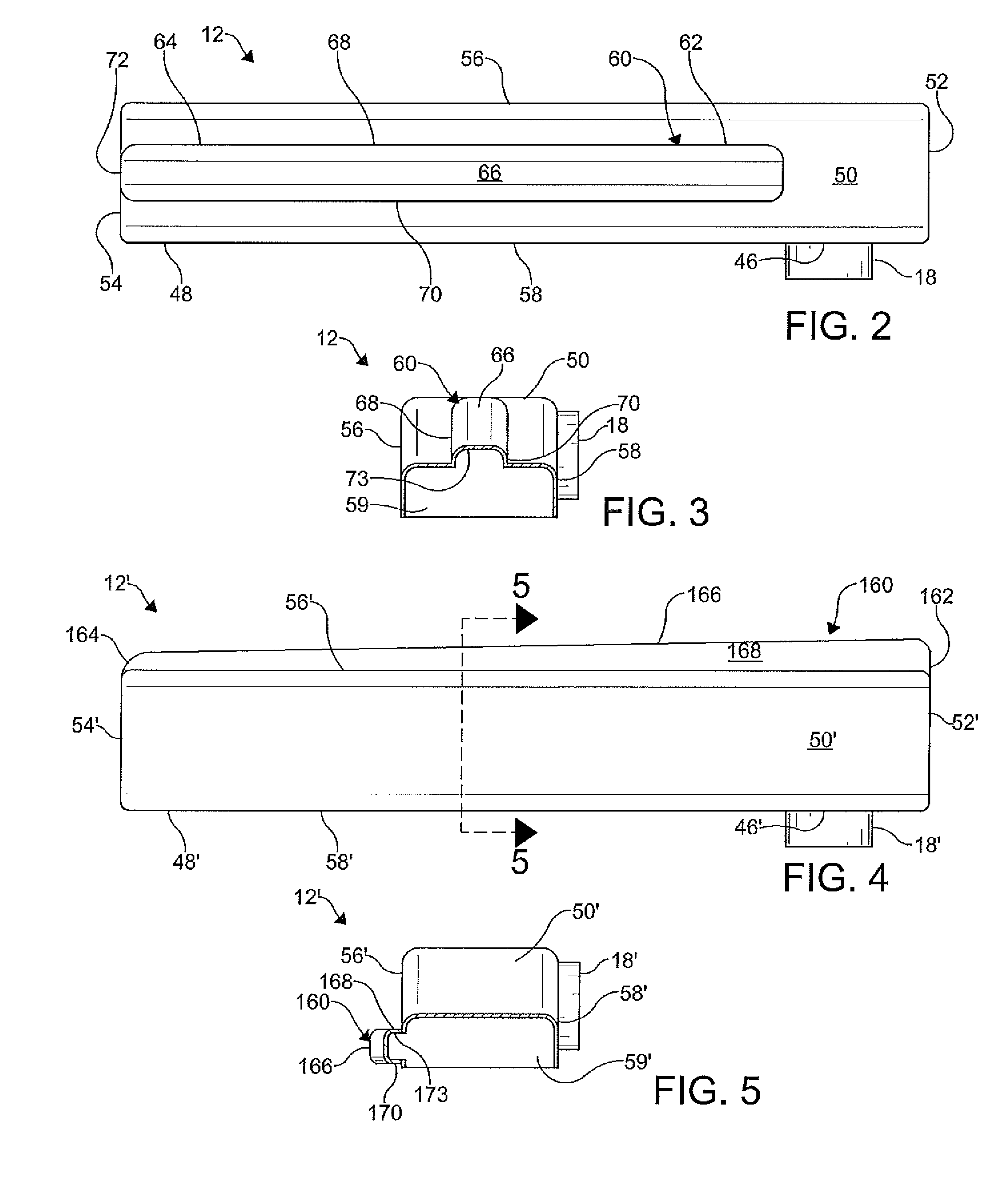
[0019]FIG. 1 depicts a heat exchanger 10 according to the present invention. The heat exchanger 10 shown is a radiator to be used in a vehicle (not shown). The heat exchanger 10 conditions a first fluid (i.e. a radiator liquid), which circulates in a fluid-conditioning system (not shown), using a second fluid (i.e. surrounding air). The fluid-conditioning system may be used to cool an engine (not shown) which powers the vehicle. Those skilled in the art will appreciate that the heat exchanger 10 can be used in various other fluid-conditioning systems, e.g. heating systems, cooling systems, and combination heating / cooling systems, related and unrelated to vehicle applications if desir...


PUM

PropertyMeasurementUnit
Fractionaaaaaaaaaa
Fractionaaaaaaaaaa
Fractionaaaaaaaaaa

Abstract

A heat exchanger configured to condition a flow of fluid therein. The heat exchanger includes a first manifold, a second manifold, and a conditioning assembly having a plurality of tubular elements extending between the first manifold and the second manifold. The first manifold includes a first end having an inlet formed therein and a second end formed opposite the first end. The first manifold is formed by at least one wall having at least one fluid flow distribution feature integrally formed therein. The at least one fluid flow distribution feature includes a channel extending substantially parallel to a general direction of flow of the fluid through the first manifold.

Description

FIELD OF THE INVENTION[0001]The present invention relates generally to a heat exchanger and, more particularly, to a heat exchanger manifold with a fluid flow distribution feature formed therein.BACKGROUND OF THE INVENTION[0002]Conventional radiators are usually provided with a cooling portion in which a radiator liquid is cooled, and two manifolds which are connected to the cooling portion at opposite ends. The first manifold receives the hot radiator liquid before it is led into the cooling portion. The second manifold receives the radiator liquid after it has passed through the cooling portion. The cooling portion usually includes a plurality of tubular elements arranged in parallel which lead the radiator liquid between the manifolds. Surrounding air flows in spaces between the tubular elements so that the radiator liquid is subjected to cooling within the tubular elements. Heat transfer elements of various kinds, e.g. in the form of thin folded fins, are usually arranged in the...

Claims


Application Information

Patent Timeline
IPC IPC(8): F28F9/02B21D53/02
CPCB21D53/02F28F9/0265F28F9/0224F28F2009/029Y10T29/49389
Inventor GOENKA, LAKHI NANDLAL
Owner HANON SYST
Features
  • R&D
  • Intellectual Property
  • Life Sciences
  • Materials
  • Tech Scout
  • Unparalleled Data Quality
  • Higher Quality Content
  • 60% Fewer Hallucinations
Learn More