Manufacturing method of electric contact and manufacturing equipment of electric contact

a manufacturing method and technology of electric contact, applied in the direction of manufacturing tools, non-electric welding apparatus, capacitors, etc., can solve the problems of unclear quality of joining between different metals, and achieve the effects of reducing the time required for joining, improving productivity, and reducing the flow area of plasti

Inactive Publication Date: 2011-05-05
FUJI ELECTRIC FA COMPONENTS & SYST CO LTD
View PDF9 Cites 10 Cited by
  • Summary
  • Abstract
  • Description
  • Claims
  • Application Information

AI Technical Summary

Benefits of technology

[0023]That is, the manufacturing method is different from a method where members are joined to each other by using plastic flow as in the friction stir welding, in addition, different from a method where members to be joined are melted for diffusion welding. The manufacturing method is designed such that the metal base and the contact are joined by solid state diffusion welding by using frictional heat caused by the rotational tool and pressing pressure of the rotational tool. Therefore, time required for joining can be reduced, leading to improvement in productivity. Moreover, since pressing depth of the rotational tool can be decreased to the minimum necessary depth, dimension stability can be improved, and a dent, an impression, contact marks, discoloration and the like can be suppressed to appear on the contact. Furthermore, pressing depth of the rotational tool is controlled, and thereby an electric contact having substantially no fluctuation in quality can be stably produced.
[0040]According to the invention, the rotational tool is pressed into the metal base while being rotated, and thereby the frictional heat caused by the rotational tool is transferred to the contact surfaces of the metal base and the contact, and thereby solid state diffusion welding is performed between the contact surfaces. Then, the rotational tool is retracted from the metal base, and thus joining between the metal base and the contact is completed. In this way, the metal base and the contact are joined by solid state diffusion welding by using frictional heat caused by the rotational tool and pressing by the rotational tool. Therefore, time required for joining can be reduced, leading to improvement in productivity. Moreover, pressing depth of the rotational tool is decreased to the minimum necessary depth, and thus a plastic flow area can be reduced. Therefore, dimension stability can be improved, and a dent, an impression, contact marks, discoloration and the like can be suppressed to appear on the contact.

Problems solved by technology

In the friction stir welding, joining between the same metals (for example, each member including aluminum) has been mainly performed so far, and joining between different metals such as a contact including silver-based material and a metal base including copper alloy material, has not been achieved, therefore joint quality has been unclear in such joining between different metals.

Method used


Image

  • Manufacturing method of electric contact and manufacturing equipment of electric contact
  • Manufacturing method of electric contact and manufacturing equipment of electric contact
  • Manufacturing method of electric contact and manufacturing equipment of electric contact

Examples


Embodiment Construction

[0050]Hereinafter, a preferred embodiment of manufacturing equipment of an electric contact of the invention will be described with reference to drawings. The manufacturing equipment of an electric contact is intended to obtain an electric contact by joining a metal base 1 with a contact 3. As shown in FIGS. 3A and 3B, the metal base 1 in the embodiment extends in an approximately belt like manner with a certain length, and is in a configuration where both side portions 1a and 1a of the metal base are folded to the outside with respect to a middle portion 1b. Square contacts 3 and 3 are joined to bottoms of the side portions 1a and 1a of the metal base 1 respectively.

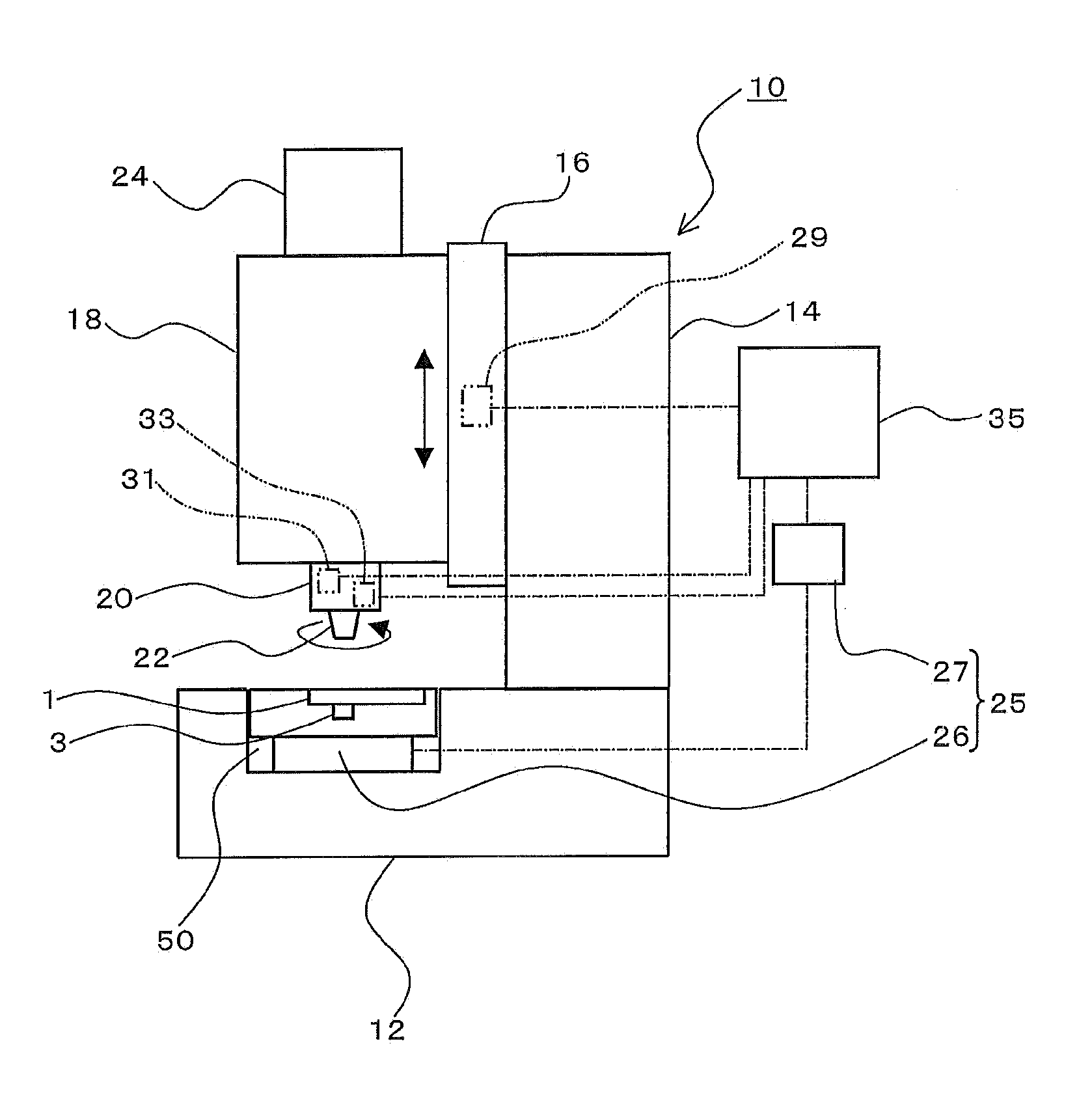
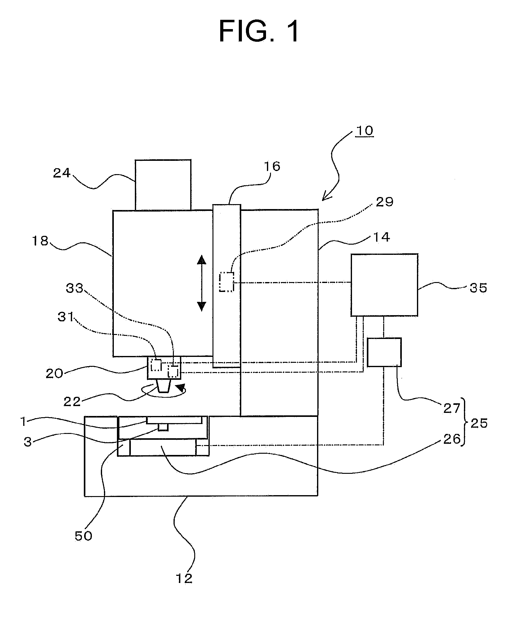
[0051]FIG. 1 shows a schematic block diagram of manufacturing equipment 10 of an electric contact of the embodiment (hereinafter, called ‘manufacturing equipment 10’). As shown in the figure, the manufacturing equipment 10 has a fixing plate 12 for fixing a jig 50 for superimposing and supporting the metal base 1 and th...


PUM

PropertyMeasurementUnit
thicknessaaaaaaaaaa
diameteraaaaaaaaaa
heightaaaaaaaaaa

Abstract

A manufacturing method of an electric contact and manufacturing equipment of the electric contact. A contact and a metal base are superimposed and support by a jig, and a rotational tool, which rotates at a predetermined speed and advances / retracts to / from the jig, is pressed into a surface, which is not contacted with the contact, of the metal base while being rotated, so that the contact and the metal base are joined by solid state diffusion welding by using frictional heat generated by friction between the rotational tool and the metal base, and then the rotational tool is retracted from the metal base.

Description

[0001]This application is the national phase of international application number PCT / JP2009 / 000142, filed Jan. 16, 2009, and claims the benefit of priority of Japanese application 2008-028597, filed Feb. 8, 2008. The disclosures of the international application and the Japanese priority applications are incorporated herein by reference.BACKGROUND OF THE INVENTION[0002]1. Field of the Invention[0003]The present invention relates to a manufacturing method of an electric contact used for an electromagnetic switch, an electromagnetic contactor, a circuit breaker and the like, and relates to a manufacturing equipment of the electric contact.[0004]2. Description of the Related Art[0005]For example, an electric contact for an electromagnetic switch, an electromagnetic contactor and the like are configured such that a movable-side contact and a fixed-side contact are contacted and separated to / from each other so as to switch an electric circuit, thereby ON / OFF operation of electrical connec...

Claims


Application Information

Patent Timeline
Patent Type & Authority Applications(United States)
IPC IPC(8): H01R43/04B23P19/00
CPCB23K2201/38H01H11/041B23K20/123B23K20/1265Y10T29/49218Y10T29/5327Y10T29/49211Y10T29/53209Y10T29/49208Y10T29/4921Y10T29/49213B23K2101/38
Inventor IMAMURA, SEIJITADA, SHINJIAKIMOTO, MAMORUYAMAMOTO, YUUICHISHIBAYANAGI, TOSHIYA
Owner FUJI ELECTRIC FA COMPONENTS & SYST CO LTD
Why Eureka
Try Eureka