Extension tip sleeve for wind turbine blade

a technology of wind turbine blades and extension sleeves, which is applied in the direction of machines/engines, mechanical equipment, transportation and packaging, etc., can solve the problems of cumbersome modification and inability to be done uptower

Active Publication Date: 2014-07-03
GENERAL ELECTRIC CO
View PDF6 Cites 43 Cited by
  • Summary
  • Abstract
  • Description
  • Claims
  • Application Information

AI Technical Summary

Problems solved by technology

This modification is cumbersome and cannot be done uptower.

Method used


Image

  • Extension tip sleeve for wind turbine blade
  • Extension tip sleeve for wind turbine blade
  • Extension tip sleeve for wind turbine blade

Examples


Embodiment Construction

[0017]When introducing elements of various embodiments of the present invention, the articles “a,”“an,”“the,” and “said” are intended to mean that there are one or more of the elements. The terms “comprising,”“including,” and “having” are intended to be inclusive and mean that there may be additional elements other than the listed elements. Any examples of operating parameters are not exclusive of other parameters of the disclosed embodiments.

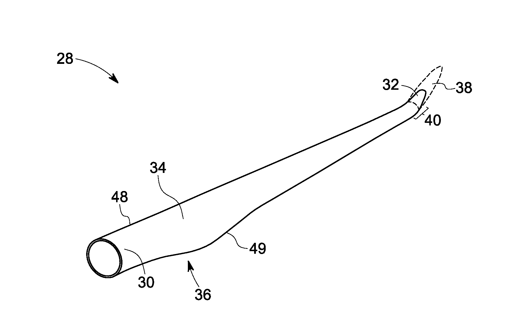
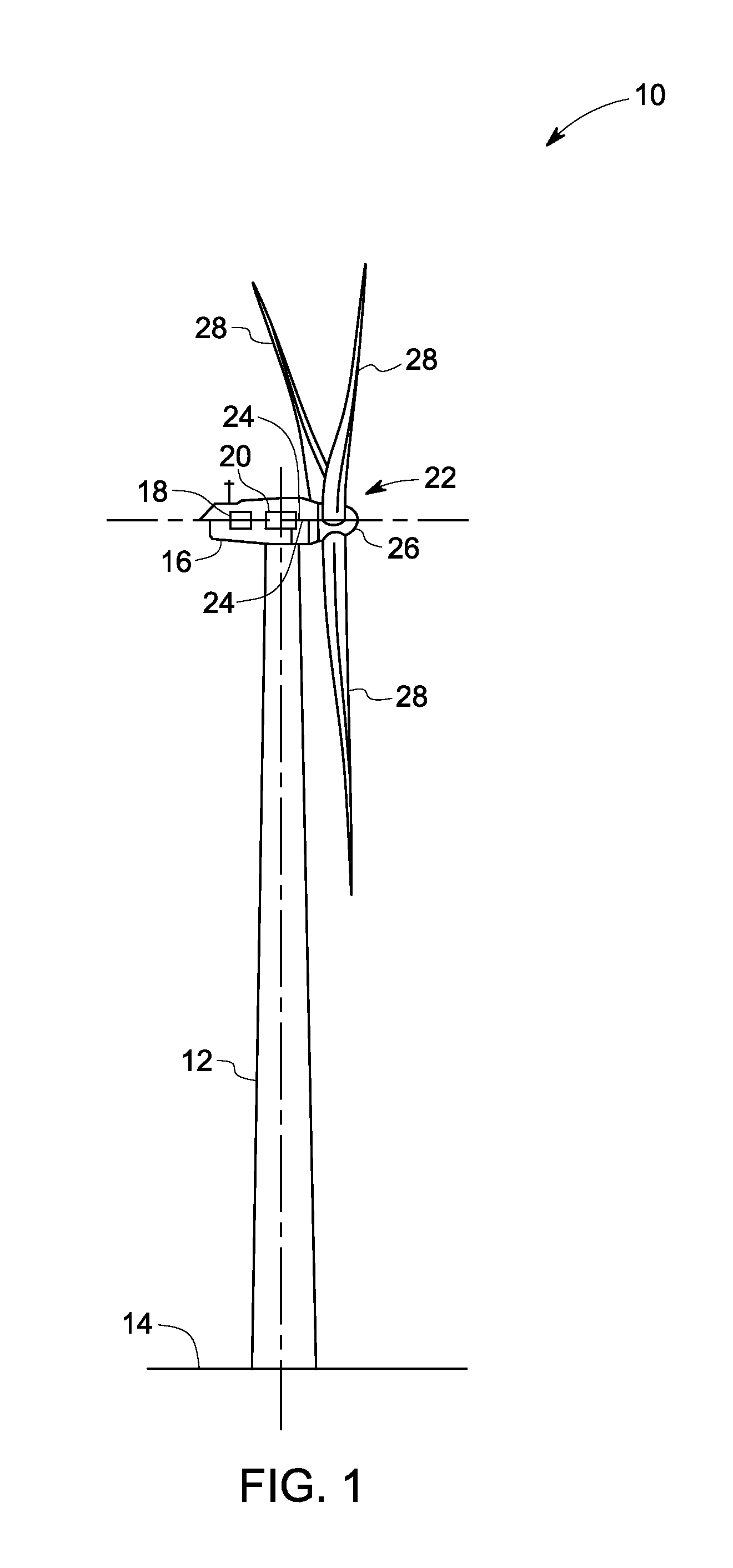
[0018]FIG. 1 is a perspective view of an exemplary wind turbine 10 in accordance with an embodiment of the present invention. In this embodiment, the wind turbine 10 is a horizontal-axis wind turbine. Alternatively, the wind turbine 10 may be a vertical-axis wind turbine. In the present embodiment, the wind turbine 10 includes a tower 12 that extends from a support surface 14, a nacelle 16 mounted on the tower 12, a generator 18 positioned within the nacelle 16, a gearbox 20 coupled to the generator 18, and a rotor 22 that is rotatably coupled ...


PUM


Abstract

A wind blade is provided. The wind blade includes a body having an aerodynamic contour extended between a blade root and a blade tip. The wind blade also includes an extension tip sleeve arranged over the blade tip. The extension tip sleeve further includes a first portion having an extension blade and one or more structural ribs arranged on a pressure side of the wind blade. The extension tip sleeve also includes a second portion having a support structure located on a suction side of the wind blade. Furthermore, the wind blade includes a fairing having an airfoil shape for covering the one or more structural ribs, and the support structure of the extension tip sleeve.

Description

BACKGROUND[0001]The present application relates generally to wind turbines and more particularly relates to wind turbine rotor blades with extension tip sleeves.[0002]Most environment friendly energy sources presently available come from wind power that is considered to be one of the cleanest. In this regard, wind turbines have gained increased attention. Wind turbines generate electricity by effectively harnessing energy in the wind via a rotor having a set of rotor blades that turns a gearbox and generator, thereby converting mechanical energy to electrical energy that may be deployed to a utility grid.[0003]To ensure that wind power remains a viable energy source, efforts have been made to increase energy output by modifying the size, configuration and capacity of wind turbines. One such modification has been to extend the tip of each wind turbine rotor blade. Such a tip extension can be employed to improve the overall efficiency and performance of a wind turbine. The tip extensi...

Claims


Application Information

Patent Timeline
Patent Type & Authority Applications(United States)
IPC IPC(8): F01D5/14
CPCF01D5/147F03D1/0675Y02E10/72
Inventor BAEHMANN, PEGGY LYNNLOGANATHAN, JAIKUMARSENGUPTA, ANINDYABALARAMUDU, VASANTH KUMARHAYASHI, STEVEN ROBERT
Owner GENERAL ELECTRIC CO
Why Eureka
Try Eureka