Ignition system having control circuit with learning capabilities and devices and methods related thereto

a technology of learning capability and control circuit, which is applied in the direction of gaseous heating fuel, household stoves or ranges, lighting and heating apparatus, etc., can solve the problems of continuous spark generation, electrical and physical noise produced by sparks, and known ignition modules for gas-fired burners, etc., to reduce the potential for igniter overheating, reduce the time, and reduce the effect of potential

Inactive Publication Date: 2014-07-03
COORSTEK INC
View PDF2 Cites 8 Cited by
  • Summary
  • Abstract
  • Description
  • Claims
  • Application Information

AI Technical Summary

Benefits of technology

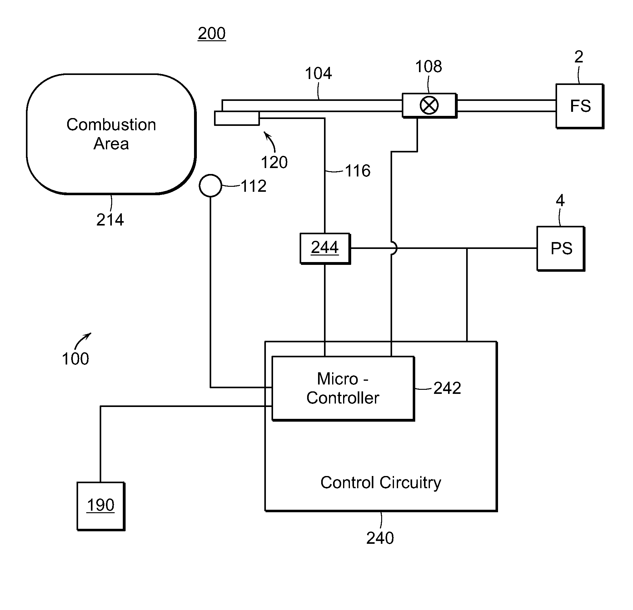
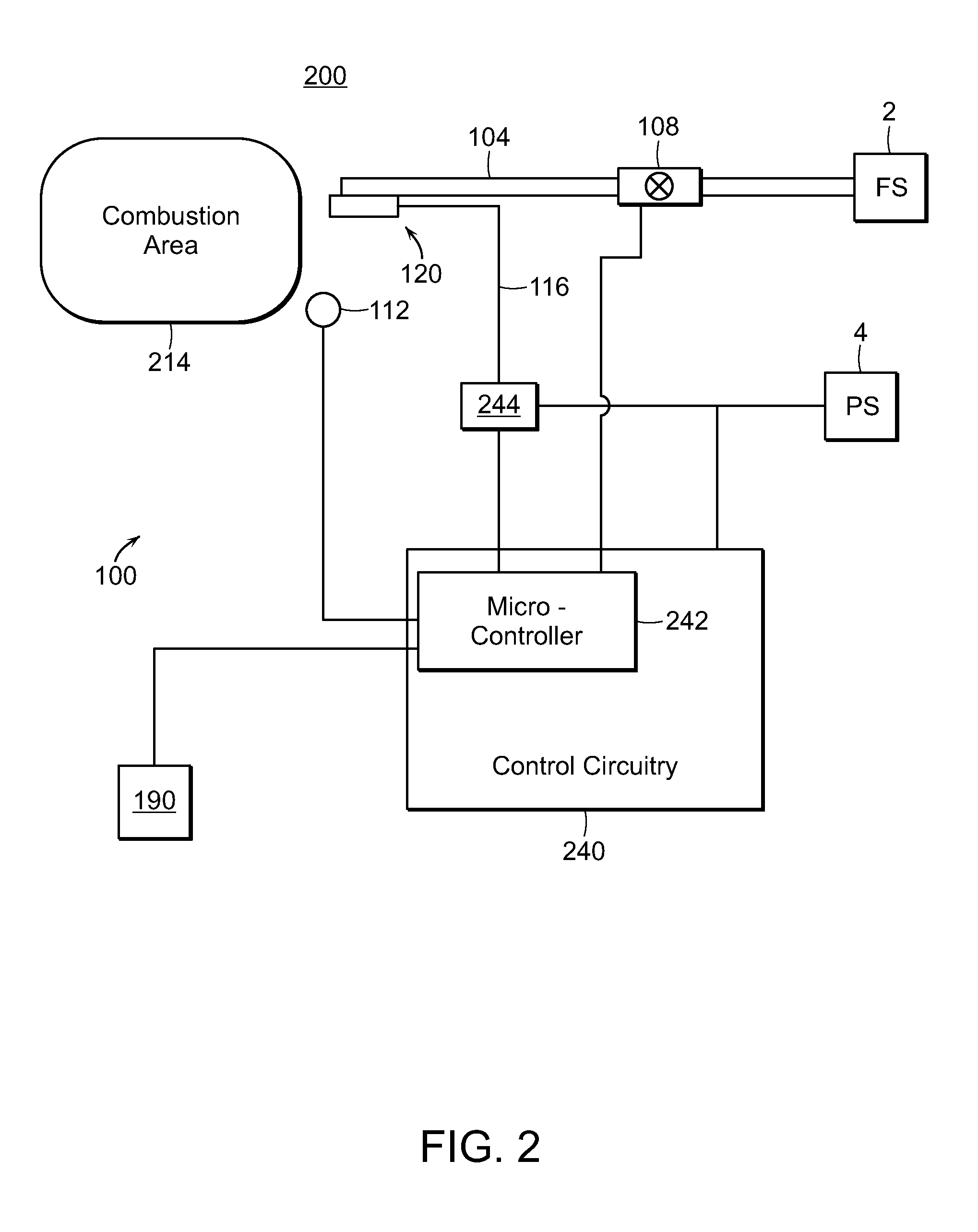
[0019]Such an ignition system further includes a flame sensing means for continuously sensing the presence or absence of a burner flame by any of a number of techniques known to those skilled in the art, including the flame rectification technique, a UV sensing technique, and a temperature measurement technique. In more particular embodiments, the flame rectification circuit design is established to eliminate the need for earthing or a ground, by the use of a comparator circuit actuated by a burner flame present between the igniter element and igniter assembly shielding.
[0028]In another illustrative embodiment, another mode of operation involves turning the igniter off or reducing the supply voltage to the igniter after ignition has been determined to occur (i.e., sensing the presence of a flame). This process minimizes, if not removes, the potential for the igniter overheating as well as limiting the time at which the igniter is at its operating temperature.
[0029]After igniter activation and after determining that ignition has occurred, the microcontroller continuously monitors the burner flame. In the event of a loss of burner flame, the microcontroller powers the igniter for a defined igniter activation period to attempt to re-light the burner. In further embodiments, multiple trials for ignition are programmed into the microcontroller. The microcontroller also is operated so that there is near instantaneous shut down of the gas valve by the flame sensing circuit thereby essentially eliminating the possible flow of raw un-lit gas to the appliance.
[0033]In yet further embodiments, the microcontroller is configured to check the flame sensing signal at the end of burner operation. In the event that the microcontroller detects that a flame is still present after the end of a burning operation, potentially indicating that the closure of the gas valve has failed to have properly occurred, the microcontroller is configured to reactivate the valve opening and closure sequence as an attempt to properly close the gas valve. A number of opening and closing sequences can be conducted as required. The microcontroller also is configurable to cause an auditory and / or a visual signal to be outputted or communicated to the user to identify the faulted condition. In this way, an indication is provided to the user to allow him or her to determine the reason for the fault, to correct the fault, and / or to have the appliance serviced.

Problems solved by technology

Problems with spark-type igniters, however, include, among other things, the electronic and physical noise produced by the spark.
Known ignition modules for gas-fired burners, however, are susceptible to malfunctions in use.
In addition, the modules are often sensitive to voltage on the neutral conductor which desensitizes the flame detection circuit and can lead to continuously generated sparks despite the presence of a flame on a burner.
If the electrical junction box is not properly wired, the ignition module will continuously spark.
Unnecessary sparking of the ignition module reduces energy efficiency and also shortens a useable life of the ignition module.
Hot surface-type igniters, however, can require significant ignition / warm-up time to resistively heat the resistance igniter sufficiently to a temperature that will ignite the fuel-air mixture (e.g., gas-air).
While certain of these efforts have been successful, other factors work so as to limit the usable service life of an igniter.
These two factors work to limit igniter usable life.
A delay is provided when recycling occurs during which the burner and related system is purged of unburned fuel or products of combustion.

Method used


Image

  • Ignition system having control circuit with learning capabilities and devices and methods related thereto
  • Ignition system having control circuit with learning capabilities and devices and methods related thereto
  • Ignition system having control circuit with learning capabilities and devices and methods related thereto

Examples


Embodiment Construction

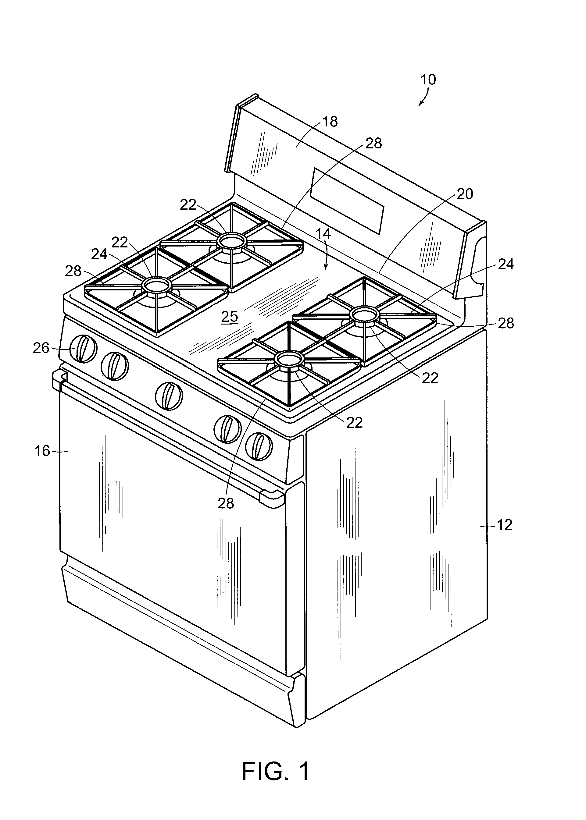
[0041]Referring now to the various figures of the drawing wherein like reference characters refer to like parts, there is shown in FIG. 1 an exemplary conventional free standing gas range 10 that includes an outer body or cabinet 12 that incorporates a generally rectangular cook top 14. An oven (not shown) is positioned below cook top 14 and has a front-opening access door 16. A range backsplash 18 extends upward of a rear edge 20 of the cook top 14 and contains various control selectors (not shown) for selecting operative features of the heating elements for cook top 14 and the oven.

[0042]In the exemplary free standing gas range 10, the cook top 14 includes four gas fueled burners 22 which are positioned in spaced apart pairs positioned adjacent each side of the cook top. Typically, each pair of burners 22 is surrounded by a recessed area 24 of the cook top 14. The recessed areas 24 are positioned below an upper surface 25 of the cook top 14 and typically serve to catch any spills ...


PUM


Abstract

Featured is an ignition system using miniaturized hot surface igniters of various types, configurations, and material systems. The ignition system includes an electronic microprocessor on which a software program is executed so as to control the operation of an igniter and all functions of the ignition system. The software program evaluates performance characteristics relating to operation of the igniter. Additionally, the software program determines operation parameters and characteristics for energizing the igniter when it determines that the operation parameters and characteristics for energizing should be updated or revised.

Description

[0001]The present application is a continuation application of U.S. patent application Ser. No. 13 / 092,839, filed on Apr. 22, 2011, which claims the benefit of U.S. Provisional Patent Application No. 61 / 327,649, filed on Apr. 23, 2010, both applications of which are incorporated herein by reference in their entireties.FIELD OF INVENTION[0002]The present invention relates to control systems for fuel burner igniters and more particularly to control systems for electrical resistance-type igniters for fuel burners and methods for determining and controlling the voltage to, and the “on time” duration for, such electrical resistance-type igniters.BACKGROUND OF THE INVENTION[0003]There are a number of appliances such as cooking ranges and clothes dryers, and heating apparatuses such as boilers and furnaces in which a combustible material, such as a combustible hydrocarbon (e.g., propane, natural gas, oil) is mixed with air (i.e., oxygen) and continuously combusted within the appliance or h...

Claims


Application Information

Patent Timeline
Patent Type & Authority Applications(United States)
IPC IPC(8): F23N5/26F23Q23/08
CPCF23Q23/08F23N5/265F24C3/126F23Q7/26F23N2227/00
Inventor CHODACKI, THOMAS A.HANAGAN, MICHAEL J.
Owner COORSTEK INC
Why Eureka
Try Eureka