Microfluidics Systems with Waste Hollow
a microfluidics and hollow technology, applied in the direction of diaphragms, electromechanical devices, water/sludge/sewage treatment, etc., can solve the problem of large-scale systems that are not designed to be portabl
- Summary
- Abstract
- Description
- Claims
- Application Information
AI Technical Summary
Problems solved by technology
Method used
Image

Examples
fourth embodiment
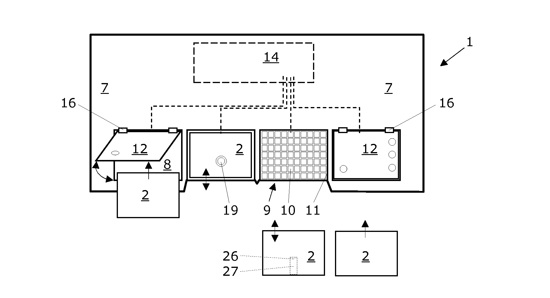
[0048]After analysis, the disposable cartridges 2 can be disposed and the electrode array 9 can be reused. Because the components of the digital microfluidics system 1 never come into contact with any samples or reagents when working with one of the embodiments of the cartridge 2, such re-usage with other disposable cartridges 2 can be immediately and without any intermediate cleaning. Because the through hole 19 of the cover plate 12 of the digital microfluidics system 1 may come into contact with samples and reagents when working with the third or fourth embodiment of the cartridge 2, such re-usage with other disposable cartridges 2 can be carried out after some intermediate cleaning or after replacement of the cover plates 12.
[0049]It is an aim of the present invention to provide removable and disposable cartridges with working films that separate the liquid droplets 23 from the electrode array 9 during manipulation of the liquid droplets 23 by electrowetting. As shown in the thr...
second embodiment
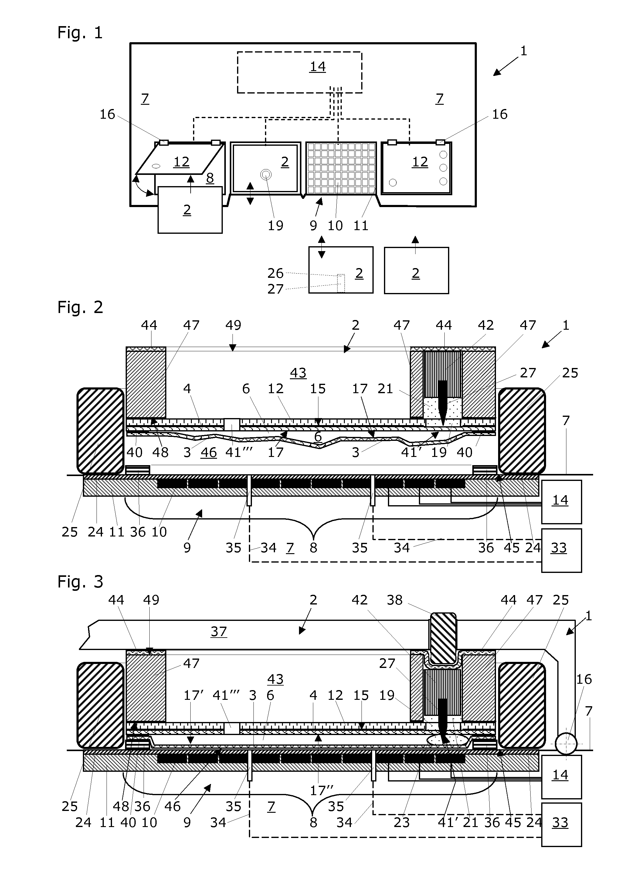
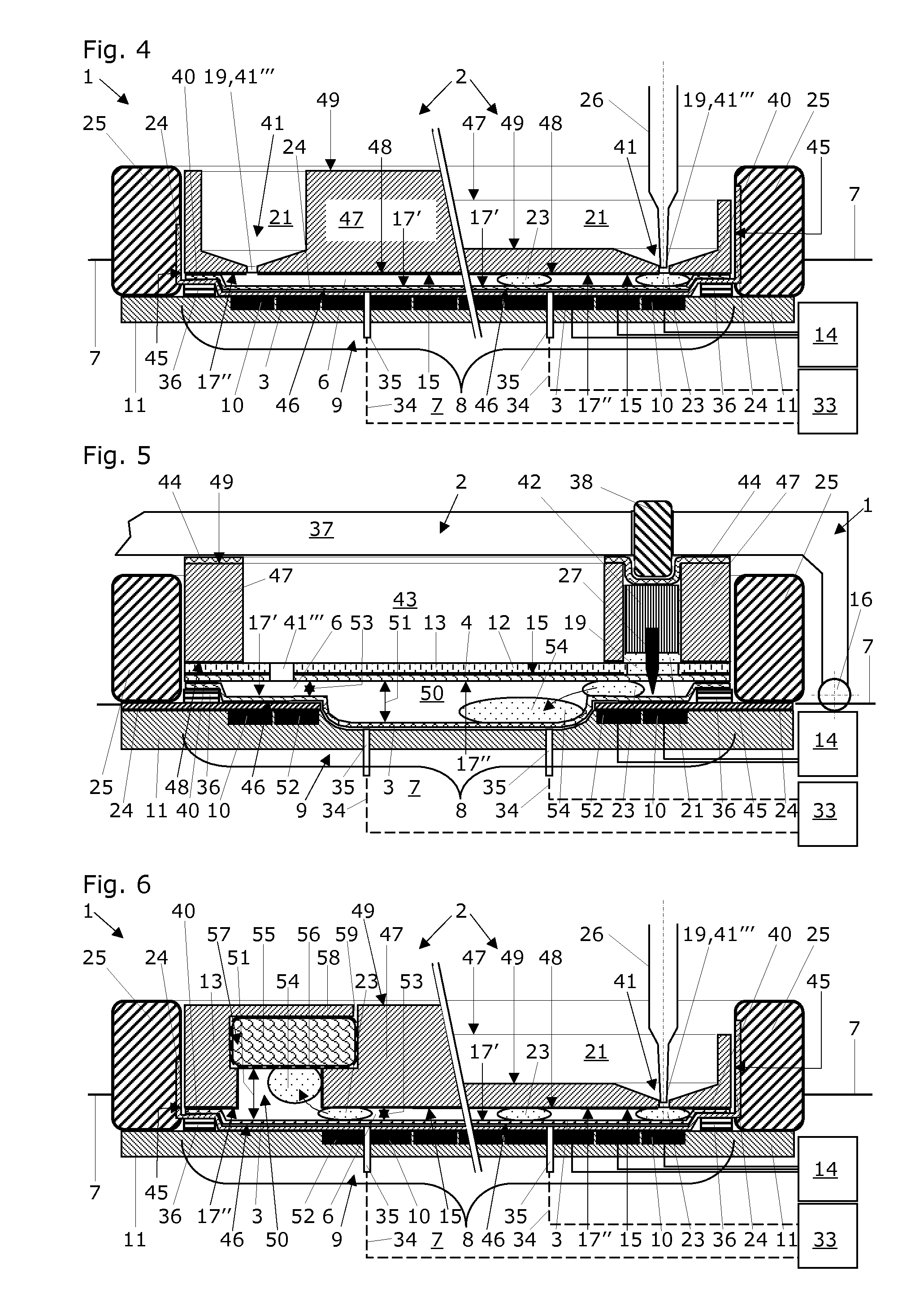
[0051]In the attached FIGS. 2, 3 and 4, especially preferred embodiments of a disposable cartridge according to a first and second embodiment are shown. In each case, the disposable cartridge 2 comprises a body 47 with at least one compartment 21 that is configured to hold therein processing liquids, reagents or samples. At least one of said compartments 21 comprises a through hole 19 for delivering at least some of its content to a gap 6 below. The disposable cartridge 2 also comprises a bottom layer 3 with a first hydrophobic surface 17′ that is impermeable to liquids and that is configured as a working film for manipulating samples in liquid droplets 23 thereon utilizing an electrode array 9 of a digital microfluidics system 1 when the bottom layer 3 of the disposable cartridge 2 is placed over said electrode array 9. The disposable cartridge 2 further comprises a top layer 4 with a second hydrophobic surface 17″ that is impermeable to liquids and that is attached to a lower surf...
first embodiment
[0053]In FIG. 3, a section view of the disposable cartridge 2 of FIG. 2 is depicted after the disposable cartridge 2 reaching its cartridge accommodation site 8 on the electrode array of a digital microfluidics system 1. The disposable cartridge 2 is configured and is hold in place by a clamp 37. On one side, the clamp 37 preferably is attached to the substrate 11 of the base unit 7 of the digital microfluidics system 1 by a hinge 16. On the other side, the clamp 37 may be attached to the substrate 11 of the base unit 7 of the digital microfluidics system 1 by e.g. a clip, a snap-lock, or a screw (not shown).
[0054]In the first embodiment of FIGS. 2 and 3, the disposable cartridge 2 further comprises a plane rigid cover plate 12 that is attached to the lower surface 48 of the body 47 of the disposable cartridge 2. The top layer 4 is attached to said rigid cover plate 12, which rigid cover plate 12 comprises through holes 19 that are located at the loading sites 41 (here at the pierc...
PUM
 Abstract
Description
Claims
Application Information
 - R&D Engineer
- R&D Manager
- IP Professional
- Industry Leading Data Capabilities
- Powerful AI technology
- Patent DNA Extraction
Browse by: Latest US Patents, China's latest patents, Technical Efficacy Thesaurus, Application Domain, Technology Topic.
© 2024 PatSnap. All rights reserved.Legal|Privacy policy|Modern Slavery Act Transparency Statement|Sitemap