
Camera registration and video integration in 3D geometry model

a technology of geometry model and camera, applied in the field of system and method of camera registration in three-dimensional (3d) geometry model, can solve the problems of difficult placement, difficult to determine the most efficient and economical use of camera resources at hand, and difficult to register a camera in the 3-d model

Inactive Publication Date: 2014-07-10
HONEYWELL INT INC
View PDF3 Cites 91 Cited by
  • Summary
  • Abstract
  • Description
  • Claims
  • Application Information

AI Technical Summary

Benefits of technology

The patent text describes a system and method for automatically placing cameras in a 3-D geometry model, which can be useful in surveillance and monitoring applications. The technical effect of this invention is that it allows for more efficient and economical use of camera resources by providing a more intuitive and higher usability for a video surveillance application. The 3-D based solutions also better visualize occlusions and allow for the integration of real video from the surveillance camera into the 3-D model. However, the automatic registration of a camera in the 3-D model is a difficult task and there is almost always some offset between the camera parameters as planned and recorded in reality.

Problems solved by technology

However, in the current state of the art, it is difficult to determine the most efficient and economical uses of the camera resources at hand.
However, automatic registration of a camera in the 3-D model is a difficult task.
For example, it is difficult to place, for a real camera installed in or around a physical building or other area, a virtual camera simulating the real camera in a 3-D model view (or scene).
Consequently, if the camera parameters imported from the planning system are directly used to get an image (e.g., video) for a coverage area of the (real) surveillance camera and then to map the image (that captures an actual view or scene) in the 3-D model, the image will not display as precise a view or scene as originally intended by a user (e.g., administrator of a camera system), providing the user with inconsistent description of a real situation.
This causes lower user awareness in many security-related applications, such as a surveillance camera system.
Conventional camera parameters registration is not only complex but also inaccurate because each reference point needs to be manually specified from a relevant 2-D image (e.g., 2-D video).
Even if it is acceptable to place the auxiliary device in the environment, how to get the device geometry data becomes another difficult problem.
However, in some instances, as illustrated in FIG. 4K, it may not be reasonable to display the video mapping effect without considering the user's (e.g., administrator's or operator's) perspective because it may lead to serious distortion of the video and confuse the user.

Method used


Image

  • Camera registration and video integration in 3D geometry model
  • Camera registration and video integration in 3D geometry model
  • Camera registration and video integration in 3D geometry model

Examples


Embodiment Construction

[0020]Development of geometry technology, high-fidelity three-dimensional (3-D) geometry models of building, such as Building Information Model (BIM) or Industry Foundation Classes (IFC), and its data are becoming more and more popular. Such technology makes it possible to display cameras and their coverage area in a 3-D geometry model (hereinafter used interchangeably with “3-D model” or “3-D building model”). Three-dimension (3-D) based solutions allow providing more intuitive and higher usability for a video surveillance application, compared to two-dimension (2-D) based solutions. This is because the 3-D based solutions, for example, better visualize occlusions by objects in field of view (FOV) of a camera, such as a surveillance camera installed in or around a building or any other area. Applicants have realized that with camera parameters, such as a location (or position) (x, y, z) or an orientation (pan, tilt, zoom), in a 3-D model, it is possible to furthermore enhance the s...


PUM


Abstract

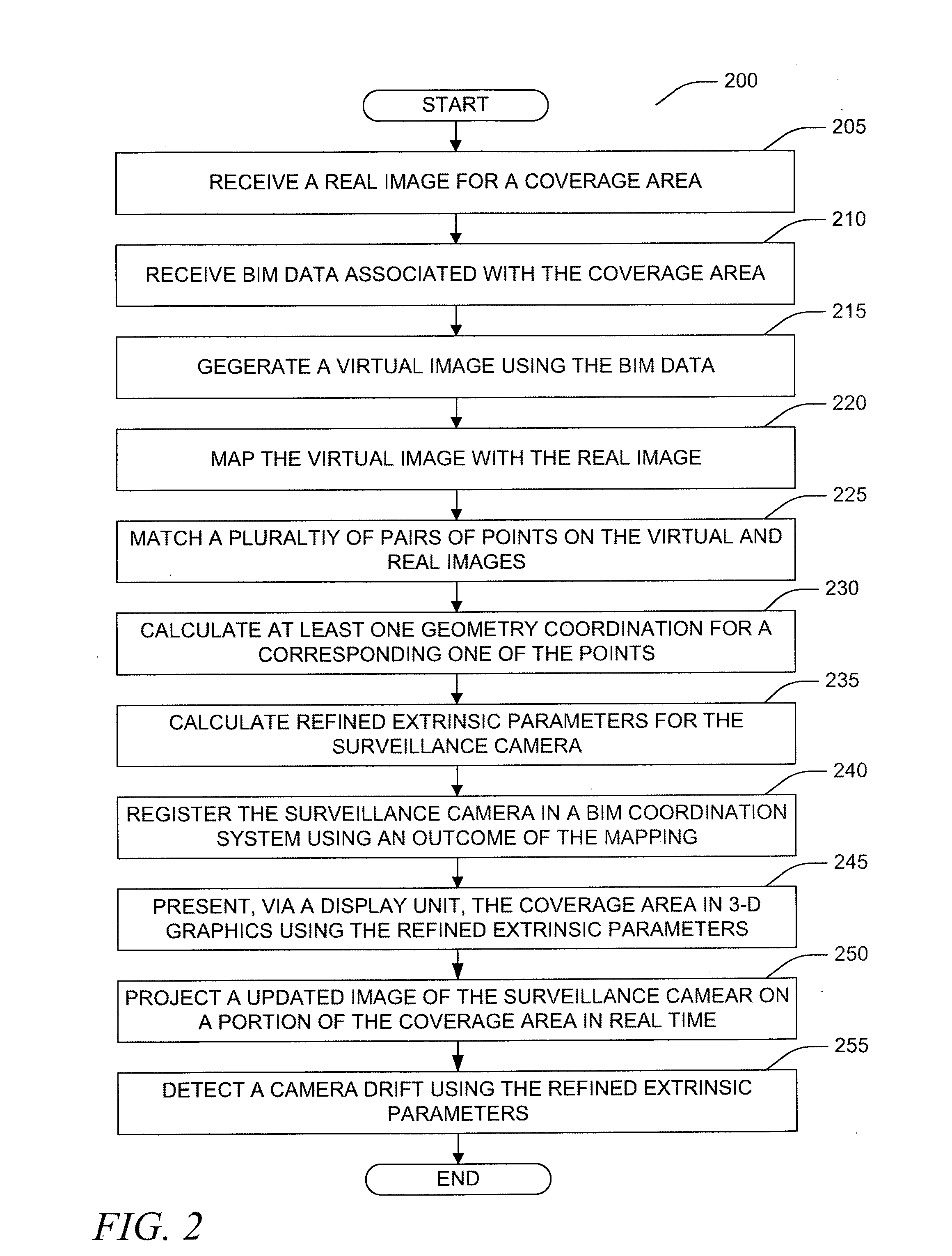
Apparatus, systems, and methods may operate to receive a real image or real images of a coverage area of a surveillance camera. Building Information Model (BIM) data associated with the coverage area may be received. A virtual image may be generated using the BIM data. The virtual image may include at least one three-dimensional (3-D) graphics that substantially corresponds to the real image. The virtual image may be mapped with the real image. Then, the surveillance camera may be registered in a BIM coordination system using an outcome of the mapping.

Description

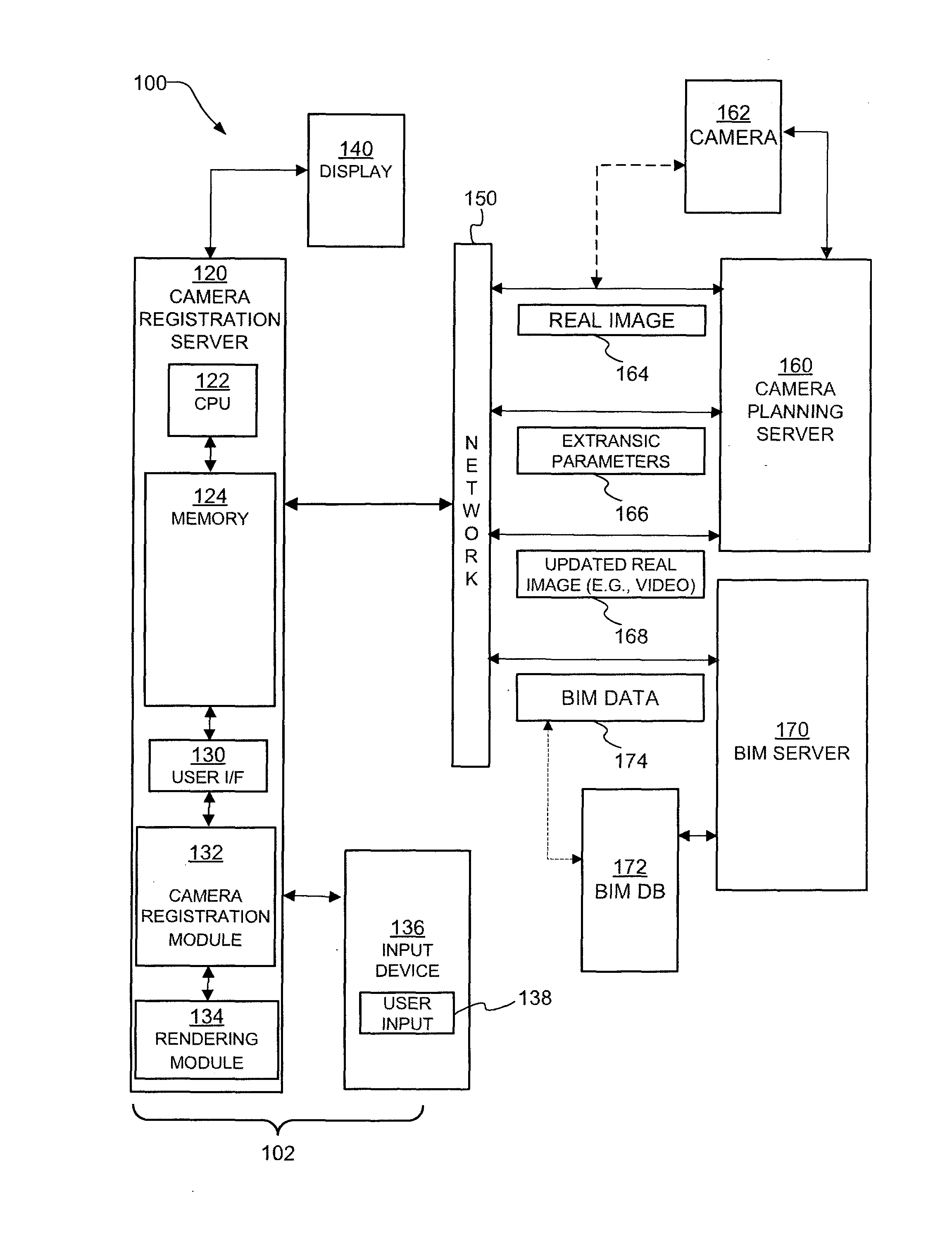
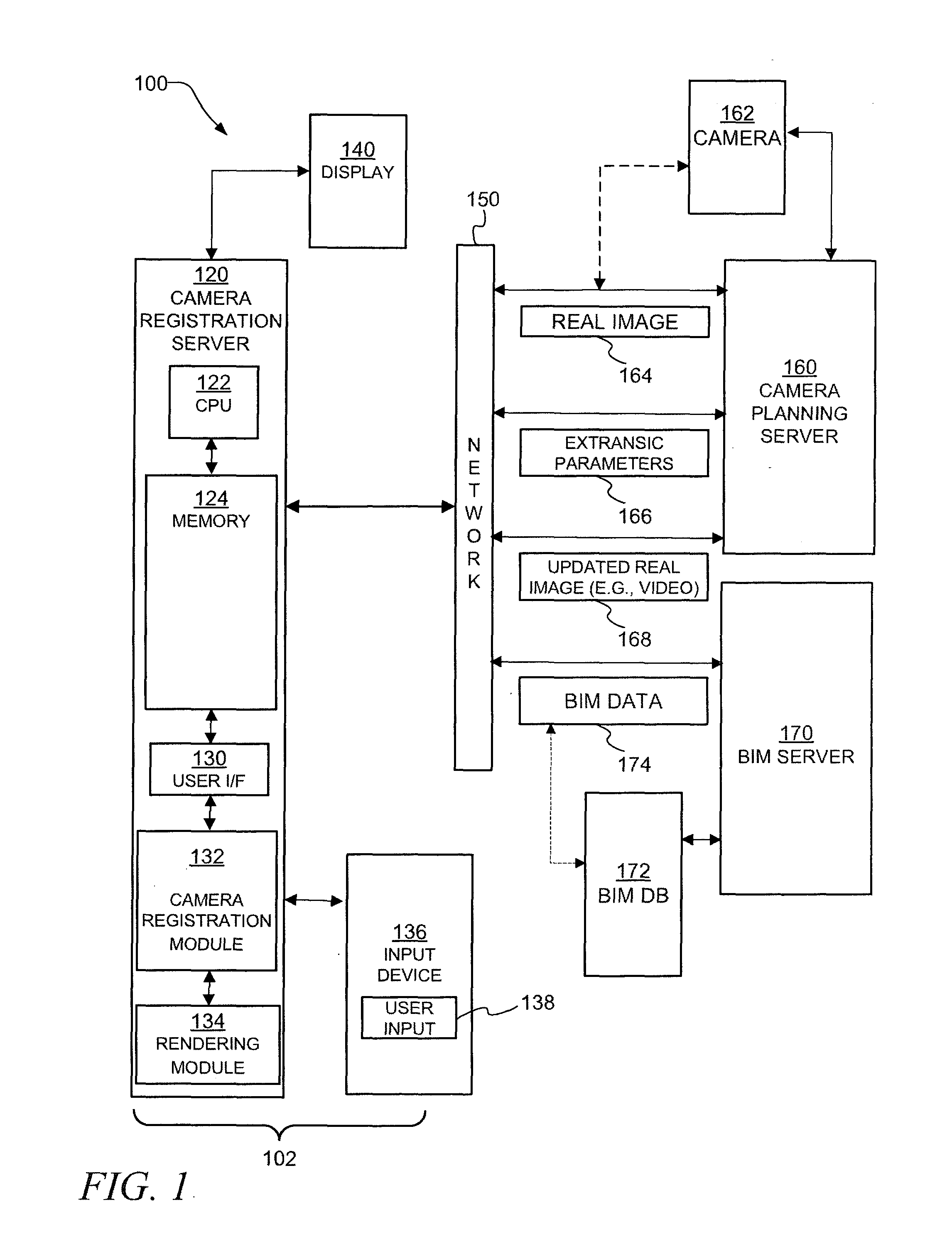
CROSS REFERENCE TO RELATED APPLICATION[0001]The present application is also related to U.S. Non-Provisional patent application Ser. No. 13 / 150,965 entitled “SYSTEM AND METHOD FOR AUTOMATIC CAMERA PLACEMENT” that was filed on the date of Jun. 1, 2011, the contents of which are incorporated by reference in their entirety.TECHNICAL FIELD[0002]The present disclosure relates to a system and method for camera registration in three-dimensional (3-D) geometry model.BACKGROUND[0003]The surveillance and monitoring of a building, a facility, a campus, or other area can be accomplished via the placement of a variety of cameras throughout the building, the facility, the campus, or the area. However, in the current state of the art, it is difficult to determine the most efficient and economical uses of the camera resources at hand.BRIEF DESCRIPTION OF THE DRAWINGS[0004]FIG. 1 is a block diagram of a system to implement camera registration in 3-D geometry model according to various embodiments of ...

Claims


Application Information

Patent Timeline
IPC IPC(8): G06T15/00
CPCG06T15/00G06T15/20G06T19/006G06T2215/16
Inventor CHEN, HENRYWANG, XIAOLIBAI, HAOROS, SAAD JPLOCHER, TOM
Owner HONEYWELL INT INC
Learn More