
Compensation System for Liquid Crystal Panel and Liquid Crystal Display Device

a liquid crystal display and liquid crystal panel technology, applied in the field of liquid crystal display techniques, can solve the problems of affecting the contrast of the large viewing angle, the contrast of the image as well as the clarity of the image also decreases, so as to improve the viewing range and improve the contrast and clarity

Inactive Publication Date: 2014-07-10
SHENZHEN CHINA STAR OPTOELECTRONICS TECH CO LTD
View PDF2 Cites 6 Cited by
  • Summary
  • Abstract
  • Description
  • Claims
  • Application Information

AI Technical Summary

Benefits of technology

[0018]The efficacy of the present invention is that to be distinguished from the state of the art. Through appropriate compensation values of the double-layer biaxial compensation film, the present invention can

Problems solved by technology

However, as the viewing angle of the liquid crystal display device increases, the contrast of the image as well as the clarity of the image also decreases, which is a result of change of birefringence of the liquid crystal molecules in the liquid crystal layer cau

Method used


Image

  • Compensation System for Liquid Crystal Panel and Liquid Crystal Display Device
  • Compensation System for Liquid Crystal Panel and Liquid Crystal Display Device
  • Compensation System for Liquid Crystal Panel and Liquid Crystal Display Device

Examples


first embodiment

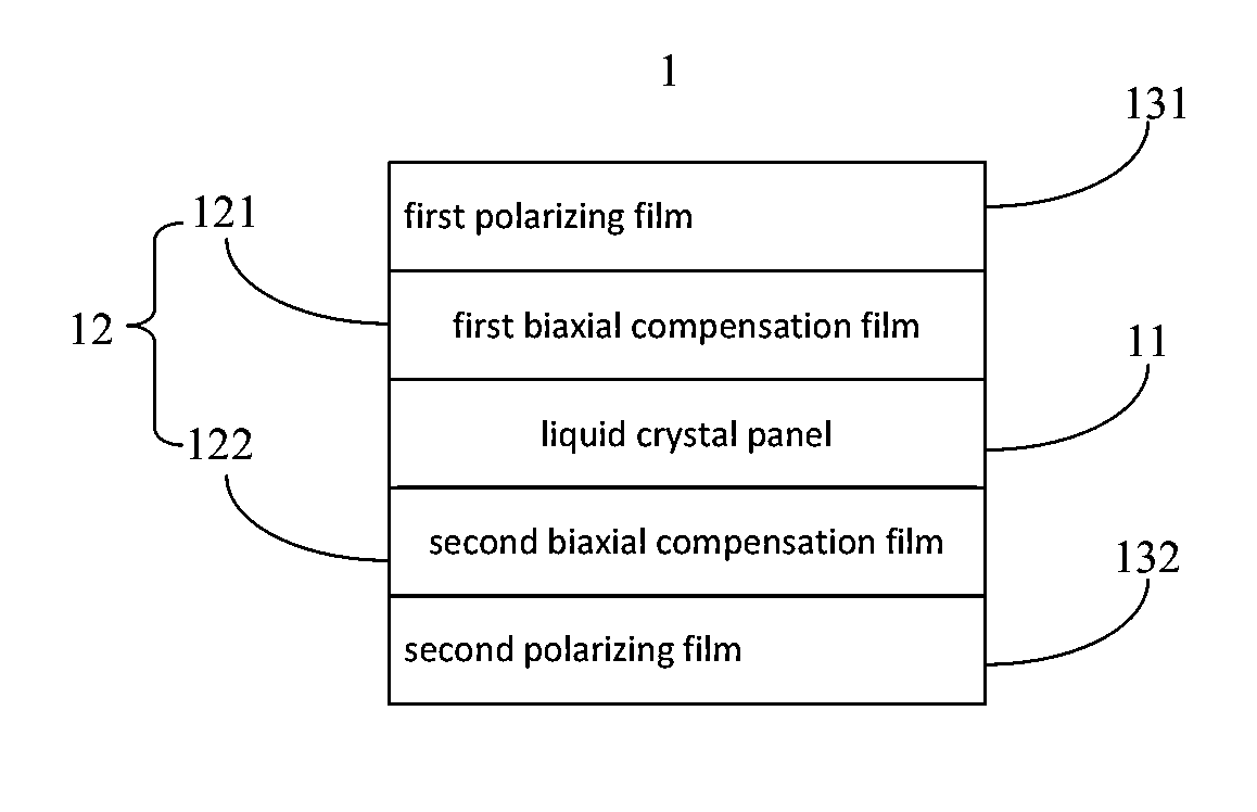
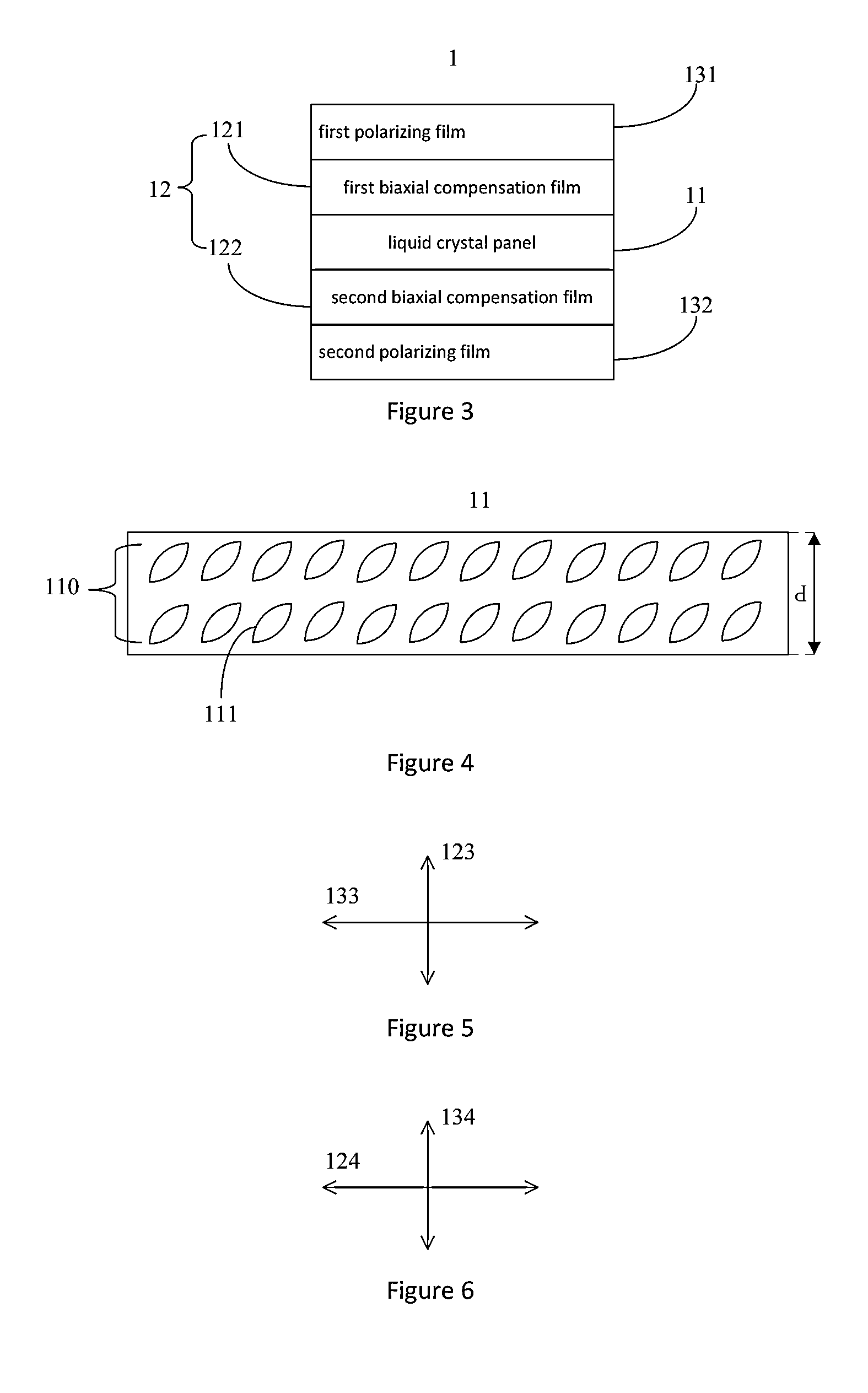
[0032]Referring to FIG. 3, FIG. 3 is a schematic view showing the structure of a liquid crystal display device of the first embodiment according to the present invention. In the instant embodiment, the liquid crystal display device 1 comprises: liquid crystal panel 11, compensation system 12 and first polarizing film 131 and second polarizing film 132.

[0033]In the instant embodiment, the liquid crystal panel 11 is a vertical alignment (VA) cell. Further referring to FIG. 4, FIG. 4 is a schematic view showing the structure of a liquid crystal panel of the first embodiment according to the present invention. The liquid crystal panel 11 is disposed with a liquid crystal layer 110 having a plurality of liquid crystal molecules 111. The liquid crystal layer has a refractive index anisotropy Δn for incident light of 550 nm wavelength, a thickness d, a liquid crystal optical path difference Δn×d and pretilt angle θ, wherein 305.8 nm≦Δn×d≦324.3 nm, and 85°≦θ≦90°.

[0034]Compensation system 12...

second embodiment

[0040]In industrial manufacturing, the first biaxial compensation film 121 and the second biaxial compensation film 122 often are the same compensation film to make the manufacturing process easier and faster. Therefore, in the second embodiment, the first biaxial compensation film 121 and the second biaxial compensation film 122 are designed to have the same compensation value range.

[0041]Referring to FIG. 9 and FIG. 10, FIG. 9 is a view showing the trend of the dark state light leakage as the compensation value changing of the liquid crystal display device of the second embodiment according to the present invention at liquid crystal optical path difference=305.8 nm; FIG. 10 is a view showing the trend of the dark state light leakage as the compensation value changing of the liquid crystal display device of the second embodiment according to the present invention at liquid crystal optical path difference=324.3 nm.

[0042]Similarly, through FIG. 9 and FIG. 10, simulation is conducted ...


PUM


Abstract

The present invention provides a compensation system for liquid crystal panel and liquid crystal display device. The compensation system includes first biaxial compensation film and second biaxial compensation film, disposed on two sides of liquid crystal panel respectively, first biaxial compensation film having planar compensation value Ro1 for incident light of 550 nm wavelength and compensation value Rth1 along thickness direction, second biaxial compensation film having planar compensation value Ro2 for incident light of 550 nm wavelength and compensation value Rth2 along thickness direction; wherein 15 nm≦Ro1≦94 nm; 35 nm≦Rth1≦214 nm; 35 nm≦Rth1≦214 nm; 14 nm≦Ro2≦101 nm; Y1≦Rth2≦Y2; Y1=0.004302×Rth12−1.96894×Rth1+259.7; Y2=−0.00234308×Rth12−0.32227×Rth1+245. As such, the present invention effectively reduces dark state light leakage of liquid crystal panel by disposing biaxial compensation films of appropriate compensation values.

Description

BACKGROUND OF THE INVENTION[0001]1. Field of the Invention[0002]The present invention relates to the field of liquid crystal displaying techniques, and in particular to a compensation system for liquid crystal panel and liquid crystal display device.[0003]2. The Related Arts[0004]As the technology progresses, the liquid crystal display device becomes the mainstream display device. However, as the viewing angle of the liquid crystal display device increases, the contrast of the image as well as the clarity of the image also decreases, which is a result of change of birefringence of the liquid crystal molecules in the liquid crystal layer caused by the changes of viewing angle. If wide-angle compensation film is used to compensate, the light leakage of the dark state image can be effectively reduced and the contrast f the image can be greatly improved in a certain viewing angle range. The theory of the compensation film is to perform correction on the phase difference caused by the li...

Claims


Application Information

Patent Timeline
IPC IPC(8): G02F1/1335G02B5/30
CPCG02F1/1335G02F1/133528G02B5/3083G02F1/133634G02F1/1393G02F2413/02G02F2413/05G02F2413/12
Inventor KANG, CHIH-TSUNGHAI, BO
Owner SHENZHEN CHINA STAR OPTOELECTRONICS TECH CO LTD
Features
  • Generate Ideas
  • Intellectual Property
  • Life Sciences
  • Materials
  • Tech Scout
  • Unparalleled Data Quality
  • Higher Quality Content
  • 60% Fewer Hallucinations
Learn More