Duty cycle balance module for switch mode power converter

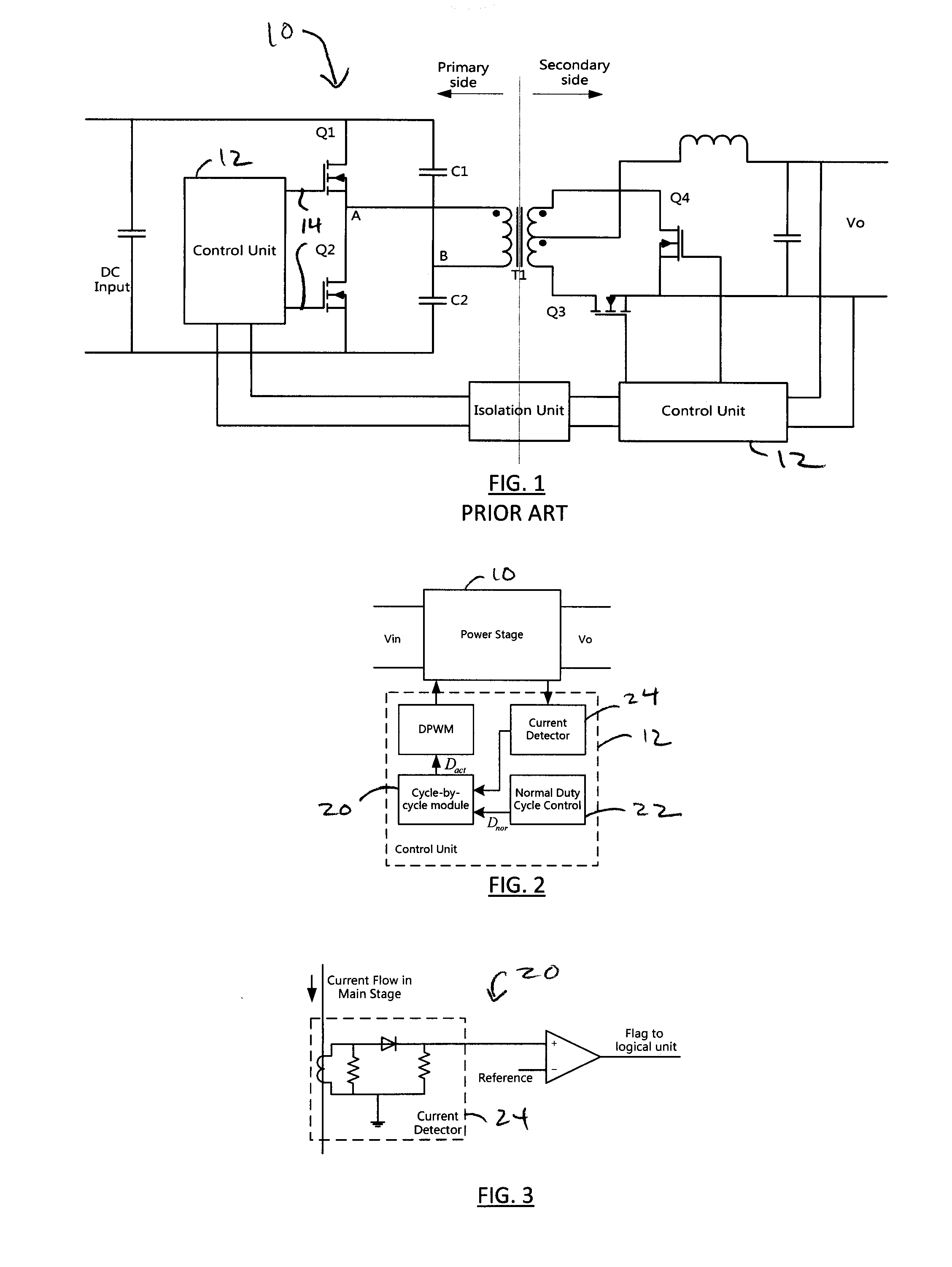
a technology of duty cycle balance and power converter, which is applied in the direction of ac-dc conversion, electric pulse generator, electric variable regulation, etc., can solve the problems of magnetic flux balance problem, voltage at center node b may drift up or down over time, and failure of flux saturation and output voltage regulation, etc., to reduce or eliminate the mismatch

Active Publication Date: 2014-07-10
ANALOG DEVICES INT UNLTD
View PDF3 Cites 37 Cited by
  • Summary
  • Abstract
  • Description
  • Claims
  • Application Information

AI Technical Summary

Benefits of technology

[0010]A duty cycle balance module (DCBM) for a switch mode power converter is presented which overcomes the problems discussed above, providing a means to balance the duty cycle or ON times of the switch drive signals dynamically—thereby reducing or eliminating the mismatch that may arise due to a current limiting mechanism.
[0014]an output block which provides output signals Dbl<sub2>—< / sub2>1 and Dbl<sub2>—< / sub2>2, the DCBM arranged such that Dbl<sub2>—< / sub2>1 and Dbl<sub2>—< / sub2>2 modify signals Dact<sub2>—< / sub2>1 and Dact<sub2>—< / sub2>2 as needed in response to the received signals so as to dynamically balance the duty cycles of the first and second signals and thereby reduce or eliminate the flux imbalance in the electromagnetic component that might otherwise arise.

Problems solved by technology

This results in a magnetic flux in the component which, if not kept balanced, can result in flux saturation and output voltage regulation failure.
However, due to variations between, for example, the capacitances of C1 and C2 and the delay times for the switch drive signals, the voltage at center node B may drift up or down over time.
But even with voltage-mode control, a magnetic flux balance problem can develop when a current in the main stage exceeds a predetermined limit threshold.
This is a duty cycle (or ON time) imbalance.
This simple cycle-by-cycle limit module always reinforces this trend, which can lead to flux saturation in the main transformer, output voltage regulation failure, and high voltage stress across the drain and source terminals of the synchronous rectifiers on the converter's secondary side.

Method used


Image

  • Duty cycle balance module for switch mode power converter
  • Duty cycle balance module for switch mode power converter
  • Duty cycle balance module for switch mode power converter

Examples


Embodiment Construction

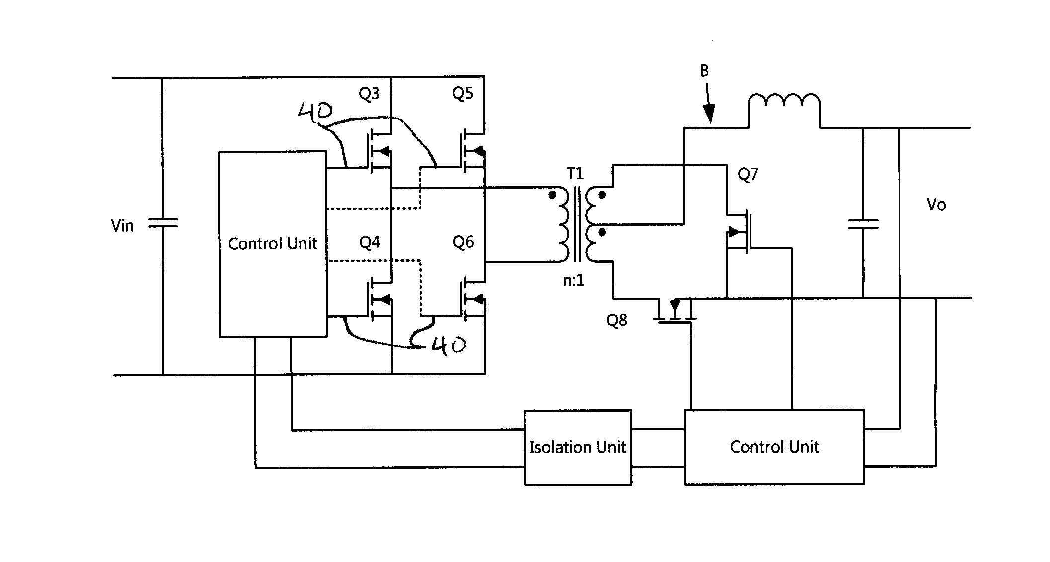
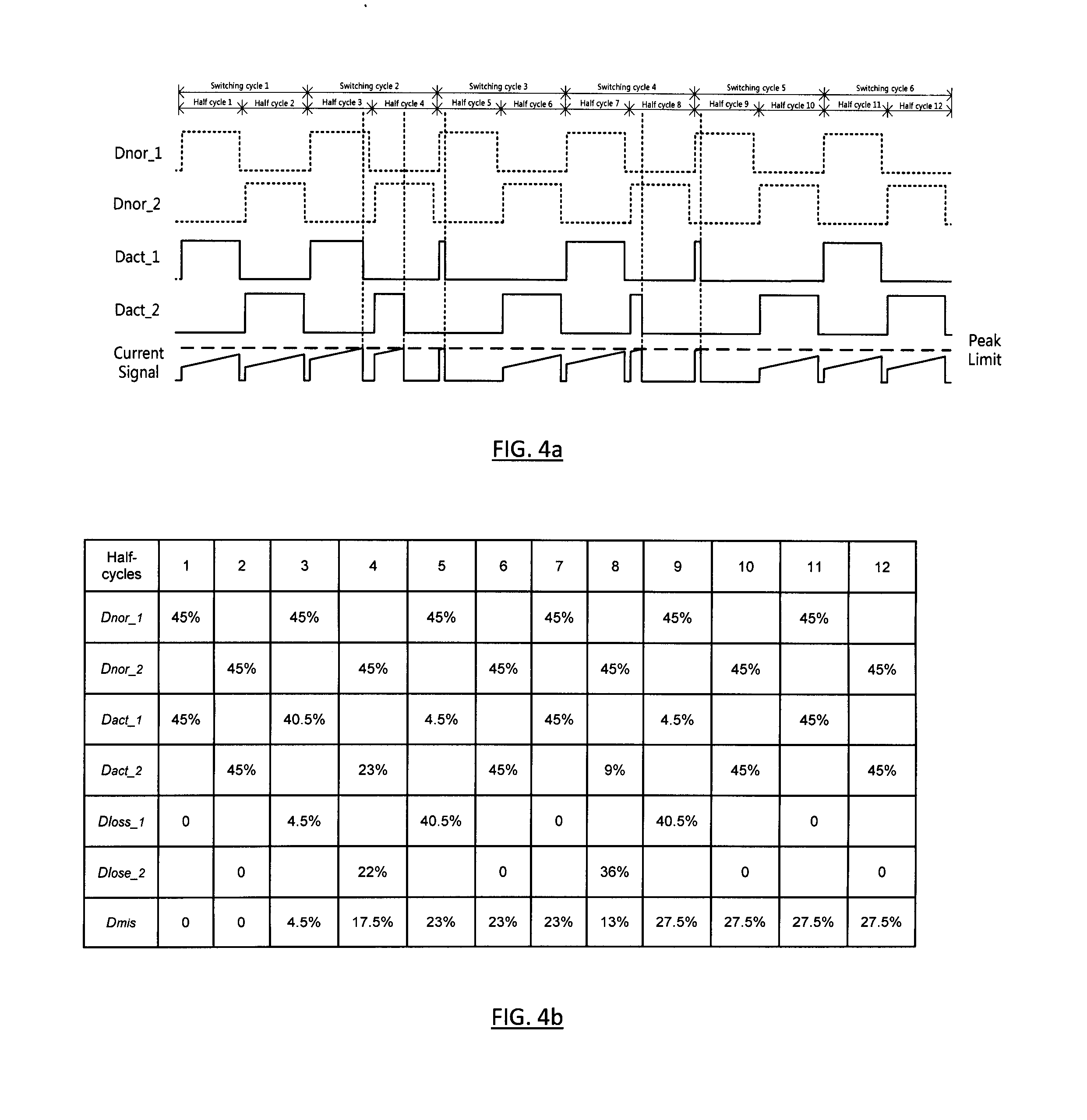
[0031]The present DCBM operates to maintain magnetic flux balance while a current limiting mechanism is affecting the operation of a switch mode converter, by reducing or eliminating the mismatch of duty cycles caused by the current limiting mechanism. In general, if the duty cycle of one switch drive signal is terminated early because of current limiting, a matched duty cycle is applied to the other switch for the next half switching cycle, regardless of the current condition. Matching the duty cycles in this way helps to maintain volt-second balancing in the transformer and to prevent transformer saturation.

[0032]For purposes of clarity, similar reference numbers will be used in the drawings to identify similar elements. As used herein, the terms “module” or “block” generally refer to, but shall not be limited to, any one or a combination of an application specific integrated circuit (ASIC), a digital, analog, or hybrid electronic circuit, a processor (shared, dedicated or group) ...


PUM


Abstract

A duty cycle balance module (DCBM) for use with a switch mode power converter. One possible half-bridge converter embodiment includes a transformer driven to conduct current in first and second directions by first and second signals during and second half-cycles, respectively. A current limiting mechanism adjusts the duty cycles of the first and second signals when a sensed current exceeds a predetermined limit threshold. The DCBM receives signals representative of the duty cycles which would be used if there were no modification by the current limiting mechanism and signals Dact<sub2>—< / sub2>1 and Dact<sub2>—< / sub2>2 representative of the duty cycles that are actually used for the first and second signals, and outputs signals Dbl<sub2>—< / sub2>1 and Dbl<sub2>—< / sub2>2 which modify signals Dact<sub2>—< / sub2>1 and Dact<sub2>—< / sub2>2 as needed to dynamically balance the duty cycles of the first and second signals and thereby reduce flux imbalance in the transformer that might otherwise arise.

Description

BACKGROUND OF THE INVENTION[0001]1. Field of the Invention[0002]This invention relates generally to switch mode power converters which include an electromagnetic component, and more particularly to techniques designed to maintain the flux balance in an electromagnetic component of such a converter.[0003]2. Description of the Related Art[0004]There are a number of switch mode converter topologies which include an electromagnetic component such as a transformer or motor; examples include half-bridge, full-bridge, 4-switch buck-boost and push-pull topologies. In normal operation, the electromagnetic component conducts a current which periodically reverses direction. This results in a magnetic flux in the component which, if not kept balanced, can result in flux saturation and output voltage regulation failure.[0005]The operation of such a converter 10 is illustrated with reference to FIG. 1, which depicts a half-bridge switch mode converter topology. On the primary side of the converte...

Claims


Application Information

Patent Timeline
Patent Type & Authority Applications(United States)
IPC IPC(8): H03K3/017H02M3/335
CPCH02M3/33507H03K3/017H02M3/33576H03K17/56H02M1/40H02M7/4803H02M1/08
Inventor OU, YINGYANGXIE, RENJIANSHENG, HUAILIANG
Owner ANALOG DEVICES INT UNLTD
Why Eureka
Try Eureka