
Bearing unit for a vehicle wheel

a technology for sealing bearings and vehicle wheels, which is applied in the direction of bearing assemblies, mechanical equipment, transportation and packaging, etc., can solve the problems of sensor insulation and leakage tightness, and achieve the effect of simple and economical manner

Active Publication Date: 2014-07-10
AB SKF
View PDF14 Cites 5 Cited by
  • Summary
  • Abstract
  • Description
  • Claims
  • Application Information

AI Technical Summary

Benefits of technology

The present invention aims to provide a bearing unit for a vehicle wheel that is simple and cost-effective, without requiring significant changes to the process of mounting the unit or using expensive devices. This would overcome the disadvantages associated with current methods of mounting the unit.

Problems solved by technology

Moreover, since it is no longer possible with the above-described configuration of the sensor to mount the cover in axial abutment against the lug of the outer ring, it is necessary to shape the cover differently to that presently known, running the further risk of no longer being able to precisely fit the cover on the lug, with the undesirable result that contaminants may possibly infiltrate between the cover and the outer ring, to the detriment of the insulation of the sensor and of the leaktightness of the unit.

Method used


Image

  • Bearing unit for a vehicle wheel
  • Bearing unit for a vehicle wheel

Examples


Embodiment Construction

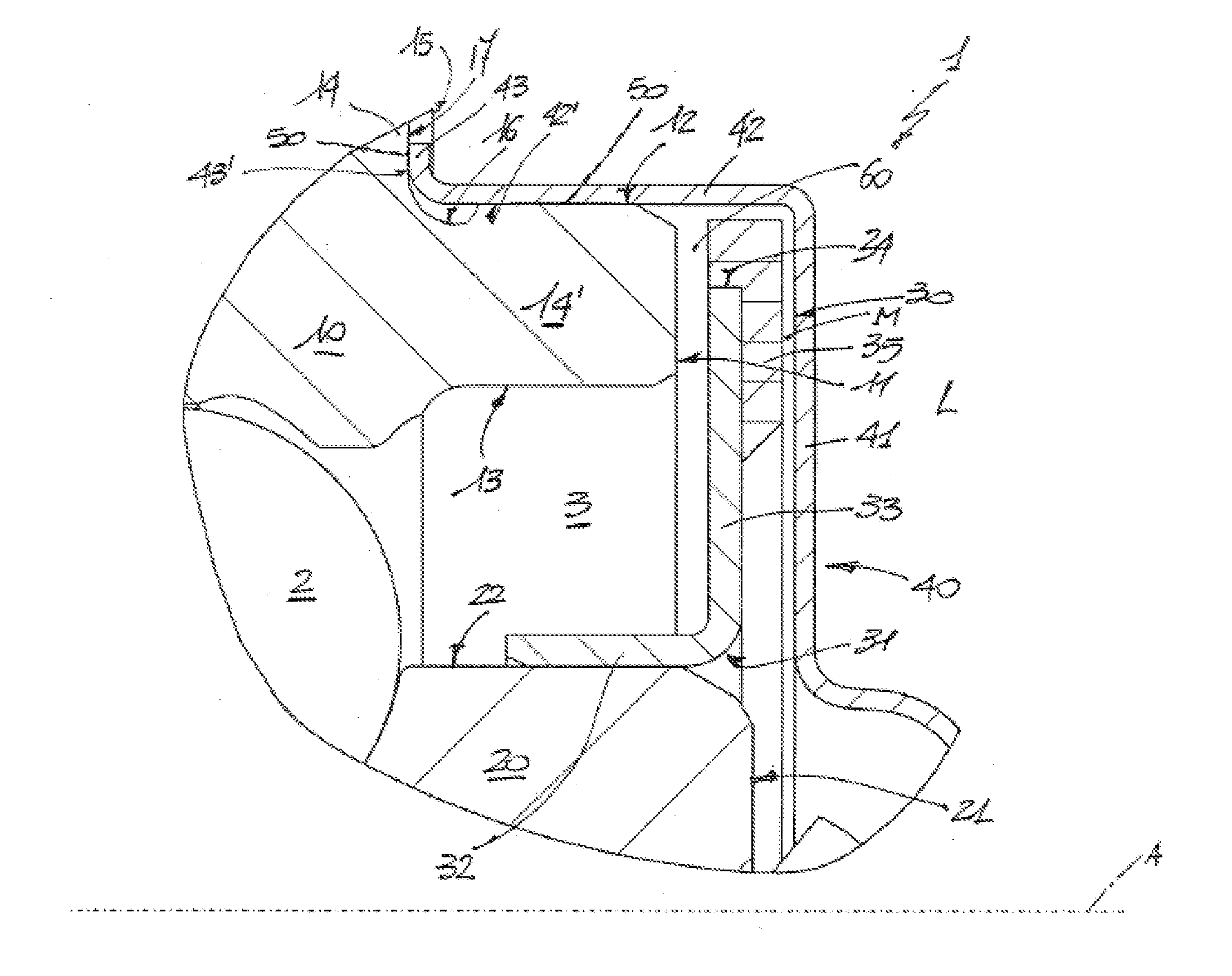
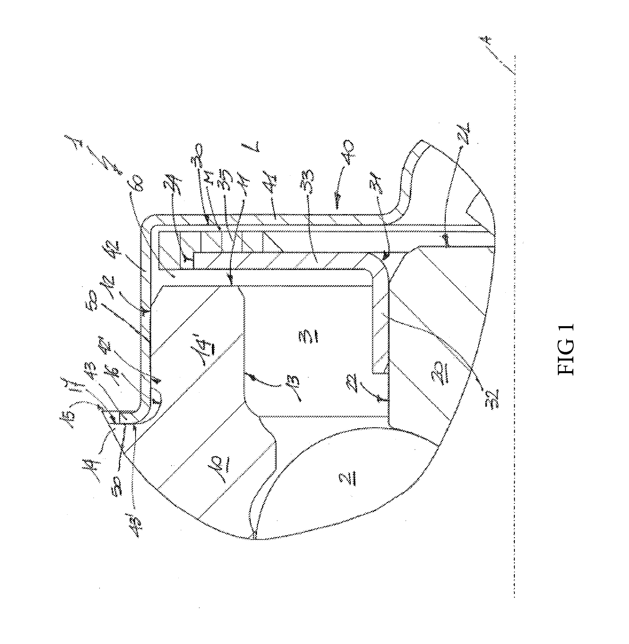
[0008]With reference to FIG. 1, 1 denotes as a whole a bearing unit for a vehicle wheel (not shown). The unit 1 has an axis of rotation A and includes a radially outer stationary ring 10 fixable to a strut (not shown) of the suspension of a vehicle and a radially inner rotatable ring 20 arranged inside the ring 10 to rotate about the axis A and with respect to the ring 10 owing to the interposition of a plurality of rolling bodies 2 (only one of which is shown).

[0009]The unit 1 further comprises a phonic wheel 30 or magnetic encoder fixed to the inner ring 20 and a protective cover 40 made of non-ferromagnetic material mounted on the outer ring 10 so as to protect the encoder 30 and close off a space 3 formed between the two rings 10 and 20.

[0010]In particular, the outer ring 10 and the inner ring 20 are axially delimited on one side L of the unit 1 by respective axial annular surfaces 11 and 21 which are transverse to the axis of rotation A, of which the surface 11 is placed in a m...


PUM


Abstract

A bearing unit for a vehicle wheel having a radially outer stationary ring provided with an axial lug, with a flange transverse to an axis of rotation and with an annular channel formed between the axial lug and the flange and delimited axially by a bottom surface. A radially inner rotatable ring defining, together with the stationary ring, a space; an encoder fixed onto the inner ring and extending outside of the space and in front of the axial lug; a protective cover mounted on the axial lug to protect the encoder and close off the space and provided with a side wall mounted on the outer cylindrical surface and having a bent edge arranged axially in abutment against the bottom surface of the annular channel; sealing means disposed between the cylindrical side wall and the tubular axial lug to seal the cylindrical side wall on the outer cylindrical surface.

Description

CROSS-REFERENCE TO RELATED APPLICATIONS[0001]This application claims priority to Italian Patent Application No. TO2013A000007 filed Jan. 8, 2013, the content of which is herein fully incorporated by reference.TECHNICAL FIELD OF THE INVENTION[0002]The present invention relates to a sealed bearing unit for a vehicle wheel. In particular, the present invention relates to a bearing unit having a radially outer stationary ring and a radially inner rotatable ring defining, together with the stationary ring, a space; an encoder fixed onto the inner ring and extending outside of the space and in front of an axial lug of the outer ring; and a protective cover mounted on the axial lug so as to protect the encoder and close off the space.BACKGROUND OF THE INVENTION[0003]In most applications, the encoder is mounted entirely between two rings inside a space, whereas, in the solution described above, the encoder extends outside of the space until it is positioned in front of the axial lug: since ...

Claims


Application Information

Patent Timeline
IPC IPC(8): F16C33/76F16C41/00F16C19/00
CPCF16C33/76F16C41/007F16C19/00F16C19/186F16C33/723F16C33/768F16C33/783F16C2326/02B60B35/18F16C33/72
Inventor BARATTI, PAOLOSERAFINI, ANDREA
Owner AB SKF
Learn More