Memory testing with selective use of an error correction code decoder

a code decoder and memory technology, applied in error detection/correction, instruments, computing, etc., can solve problems such as memory cell errors, memory cell errors, and other errors that are left unnoticed, and achieve the effect of detecting memory cell errors, avoiding other errors, and avoiding memory cell errors

a code decoder and memory technology, applied in error detection/correction, instruments, computing, etc., can solve problems such as memory cell errors, memory cell errors, and other errors that are left unnoticed, and achieve the effect of detecting memory cell errors, avoiding other errors, and avoiding memory cell errors

US20140195867A1Inactive Publication Date: 2014-07-10IBM CORP

Image

  • Memory testing with selective use of an error correction code decoder
  • Memory testing with selective use of an error correction code decoder
  • Memory testing with selective use of an error correction code decoder

Examples


Embodiment Construction

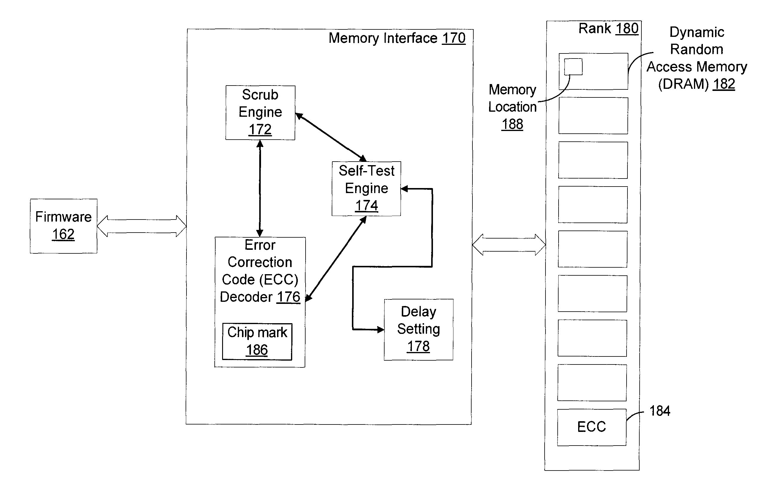
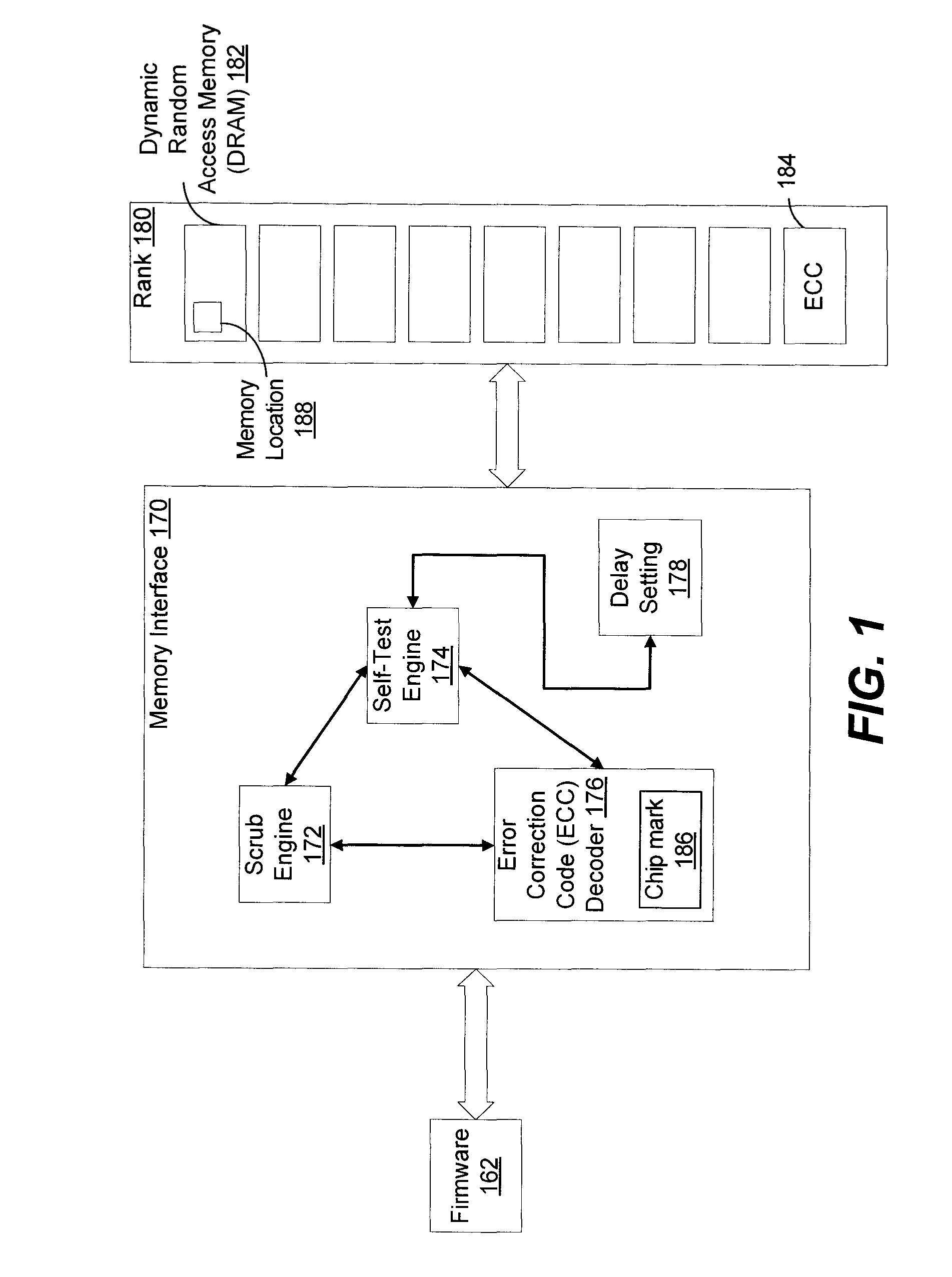
[0015]Systems and methods of performing memory testing with selective use of an error correction code (ECC) decoder are disclosed. For example, memory testing may selectively use an error correction code (ECC) decoder to direct an access (e.g., a read access or a write access) of user data associated with a memory location to the ECC decoder, while the memory location is being tested by writing test patterns to the memory location. A test pattern may be written to the memory location and compared to a value read from the memory location. A fault may be detected when the test pattern and the value read from the memory location do not match. The chances of detecting a fault may be improved by using several different test patterns designed to detect various kinds of faults (e.g., faults which may not be detectable by using other memory testing algorithms, such as parity checking).

[0016]The disclosed techniques may enable runtime memory testing by directing an access (e.g., a read acces...


PUM


Abstract

A method includes directing an access of a memory location of a memory device to an error correction code (ECC) decoder in response to receiving a test activation request indicating the memory location. The method also includes writing a test pattern to the memory location and reading a value from the memory location. The method further includes determining whether a fault is detected at the memory location based on a comparison of the test pattern and the value.

Description

BACKGROUND[0001]The present disclosure relates to memory testing, and more specifically, to memory testing with selective use of an error correction code decoder. Errors in a memory cell of a computing system may be caused by a manufacturing defect, degradation over time, breakage, electrical or magnetic interference, etc. Redundant memory cells may be used to record parity and enable detection of errors. However, parity checking may detect limited types of errors (e.g., single-bit errors), leaving other errors undetected. A suite of test patterns may be developed to detect various types of errors. For example, a first test pattern may include all 0s, a second test pattern may include all 1s, etc. The first test pattern may be written to the memory cell and then a value may be read back from the memory cell. An error in the memory cell may be detected when the value and the first test pattern do not match. When an error is not detected, memory testing may continue by writing the res...

Claims


Application Information

Patent Timeline
10 Jul 2014
Publication
US20140195867A1
IPC
G11C29/42
CPC
G11C29/00; G11C29/42; G11C29/12; G11C29/56; G11C29/52; G11C2029/0409; G11C2029/0411; G06F11/106
Inventors
GOLLUB, MARC A.; PAULRAJ, GIRISANKAR