Method and Apparatus for In-Well Wireless Control Using Infrasound Sources

a wireless control and infrasound technology, applied in the field of oil and gas wells, can solve the problems of difficult to run the wires into the well without tangling or breaking the wires, the common communication frequency band has a very limited range, and is ineffective at communicating over long distances downhol

Active Publication Date: 2014-07-17
SAUDI ARABIAN OIL CO
View PDF2 Cites 22 Cited by
  • Summary
  • Abstract
  • Description
  • Claims
  • Application Information

AI Technical Summary

Benefits of technology

[0014]Further disclosed herein is a method of measuring the depth of a wellbore. The method includes the steps of generating infrasound waves, directing the infrasound waves into the wellbore, observing the infrasound waves for resonance indicating that the waves have reached the bottom of the wellbore, and calculating the depth of the wellbore based on the number of wavelengths of infrasound waves that have entered the wellbore when the resonance is observed. In some embodiments, the method can further include inserting reflectors into the bottom of the wellbore to help reflect infrasound waves that reach the bottom of the wellbore.

Problems solved by technology

One problem with the use of wires, however, is the difficulty of running them into the well without tangling or breaking the wires.
This can be especially problematic in multilateral wells, where lateral bores can be diverging from the motherbore in different directions, and each lateral bore can have its own ICV assembly.
One problem with such systems, however, is that such common communication frequency bands have a very limited range, and are ineffective at communicating over long distances downhole.
This range problem can be exacerbated by the nature of the fluids in a wellbore, many of which have high salinity and can be dense.

Method used


Image

  • Method and Apparatus for In-Well Wireless Control Using Infrasound Sources
  • Method and Apparatus for In-Well Wireless Control Using Infrasound Sources
  • Method and Apparatus for In-Well Wireless Control Using Infrasound Sources

Examples


Embodiment Construction

[0020]The foregoing aspects, features, and advantages of the present technology will be further appreciated when considered with reference to the following description of preferred embodiments and accompanying drawings, wherein like reference numerals represent like elements. In describing the preferred embodiments of the technology illustrated in the appended drawings, specific terminology will be used for the sake of clarity. However, the embodiments are not intended to be limited to the specific terms used, and it is to be understood that each specific term includes equivalents that operate in a similar manner to accomplish a similar purpose.

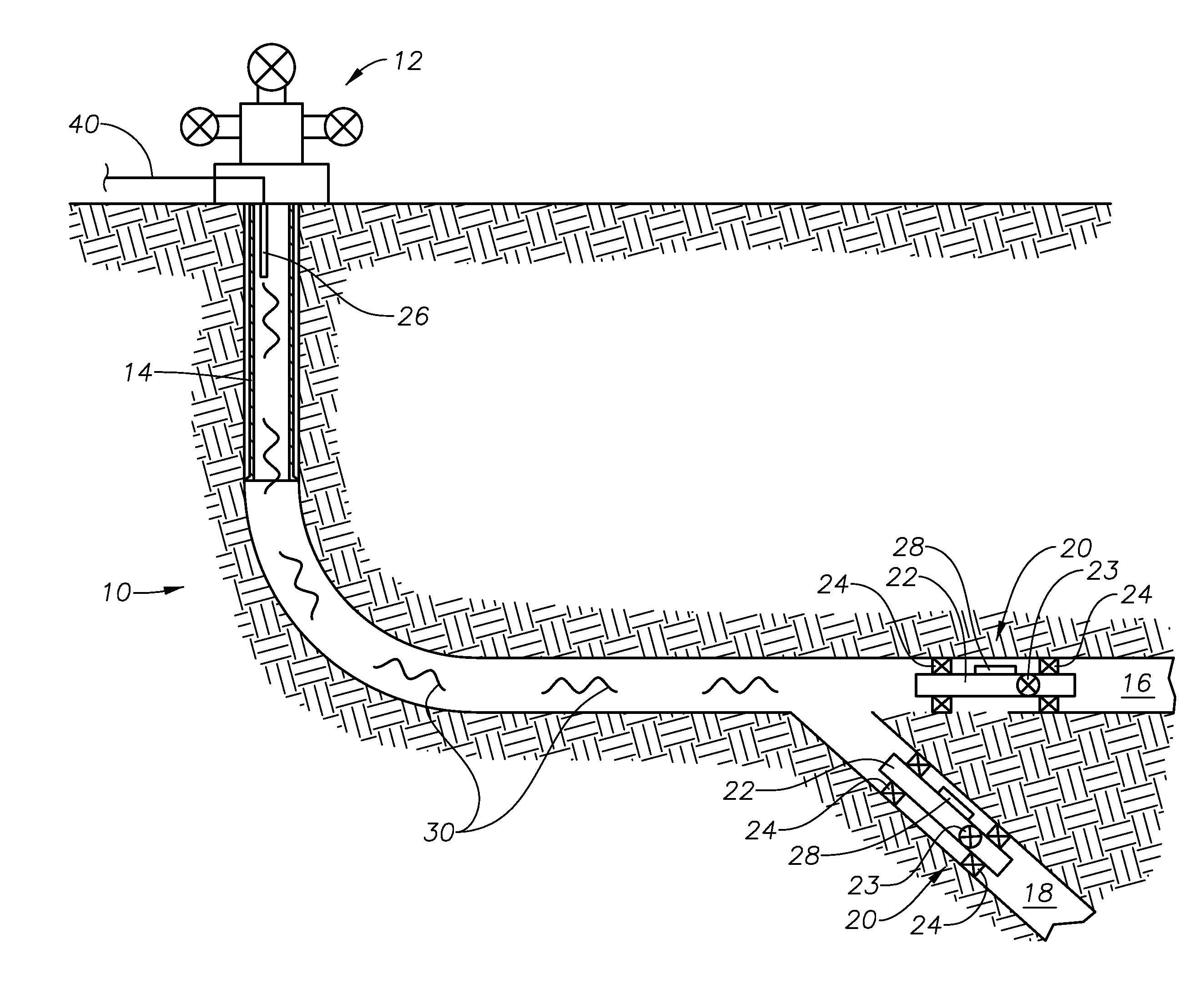
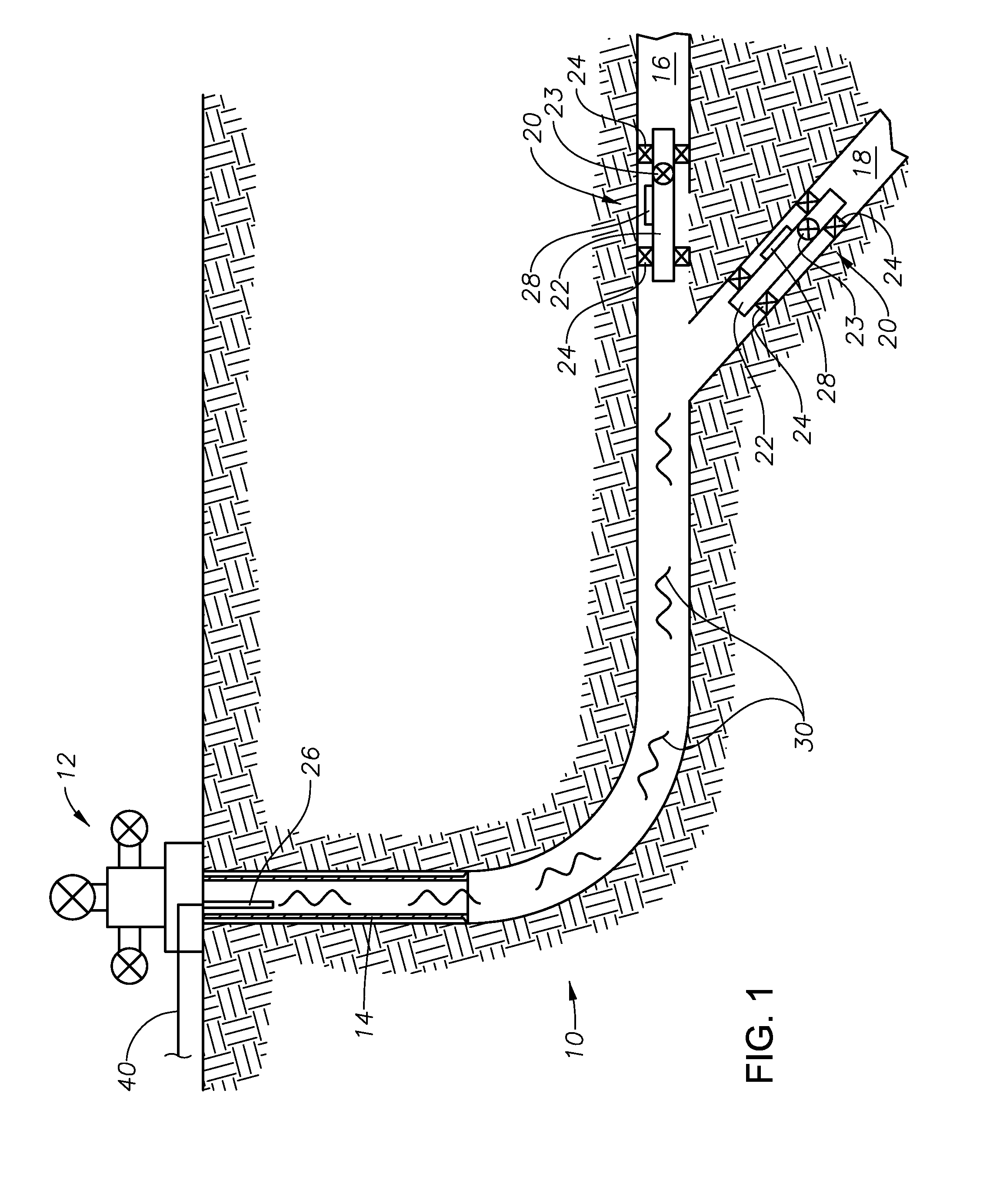
[0021]FIG. 1 shows a side view of a well 10 having a wellhead 12 at the opening thereof, and tubing 14 extending partially therein. The well 10 is a multilateral well, having a plurality of bores, including a motherbore 16, and a lateral bore 18. In the embodiment shown, the tubing 14 is not cemented and does not extend to the bottom of the w...


PUM


Abstract

A system and method for downhole data communication using an infrasound wave generator and receivers. The infrasound waves have a low frequency and a wavelength that is much larger than the transverse dimensions of the well. When the infrasound waves are directed down the well, the well will act as a wave guide for low frequency excitations. The receivers are operatively connected to inflow valves and other downhole equipment, and receive the infrasound waves. If the waves are of a predetermined frequency, the receivers command the valves to open or close, or otherwise control downhole equipment. The infrasound waves can also be used to probe well geometry and to identify fluid properties within the well.

Description

BACKGROUND OF THE INVENTION[0001]1. Field of the Invention[0002]The present technology relates to oil and gas wells. In particular, the present technology relates to control of downhole valves and equipment using infrasonic waves in oil and gas wells.[0003]2. Description of the Related Art[0004]The production of oil and gas wells typically requires the use of various valves and other downhole equipment. For example, an inflow control valve (ICV) assembly can be inserted into the well bore, and can include an inflow valve 23 that regulates the flow of fluid through the bore. The communication of commands from an operator at the surface to such valves and other downhole equipment is important to production control of the well.[0005]One way to communicate with downhole valves and other equipment is through a physical connection, such as wires. Such wires can be inserted into the hole along with, for example, an ICV assembly, and can be connected to the inflow valve 23. When the ICV ass...

Claims


Application Information

Patent Timeline
Patent Type & Authority Applications(United States)
IPC IPC(8): E21B47/00E21B47/04
CPCE21B47/04E21B47/00E21B34/066E21B47/18
Inventor NOUI-MEHIDI, MOHAMED NABILBLACK, MICHAEL JOHN
Owner SAUDI ARABIAN OIL CO
Why Eureka
Try Eureka