Method system and computer product for non-destructive object analysis

Active Publication Date: 2014-07-17
BAKER HUGHES INC
View PDF13 Cites 4 Cited by
  • Summary
  • Abstract
  • Description
  • Claims
  • Application Information

AI Technical Summary

Problems solved by technology

A variance in any of these tolerances can cause the part and/or the machine as a whole not to function for its intended purpose.
Additionally, or in the alternative, a va

Method used


Image

  • Method system and computer product for non-destructive object analysis
  • Method system and computer product for non-destructive object analysis
  • Method system and computer product for non-destructive object analysis

Examples


Embodiment Construction

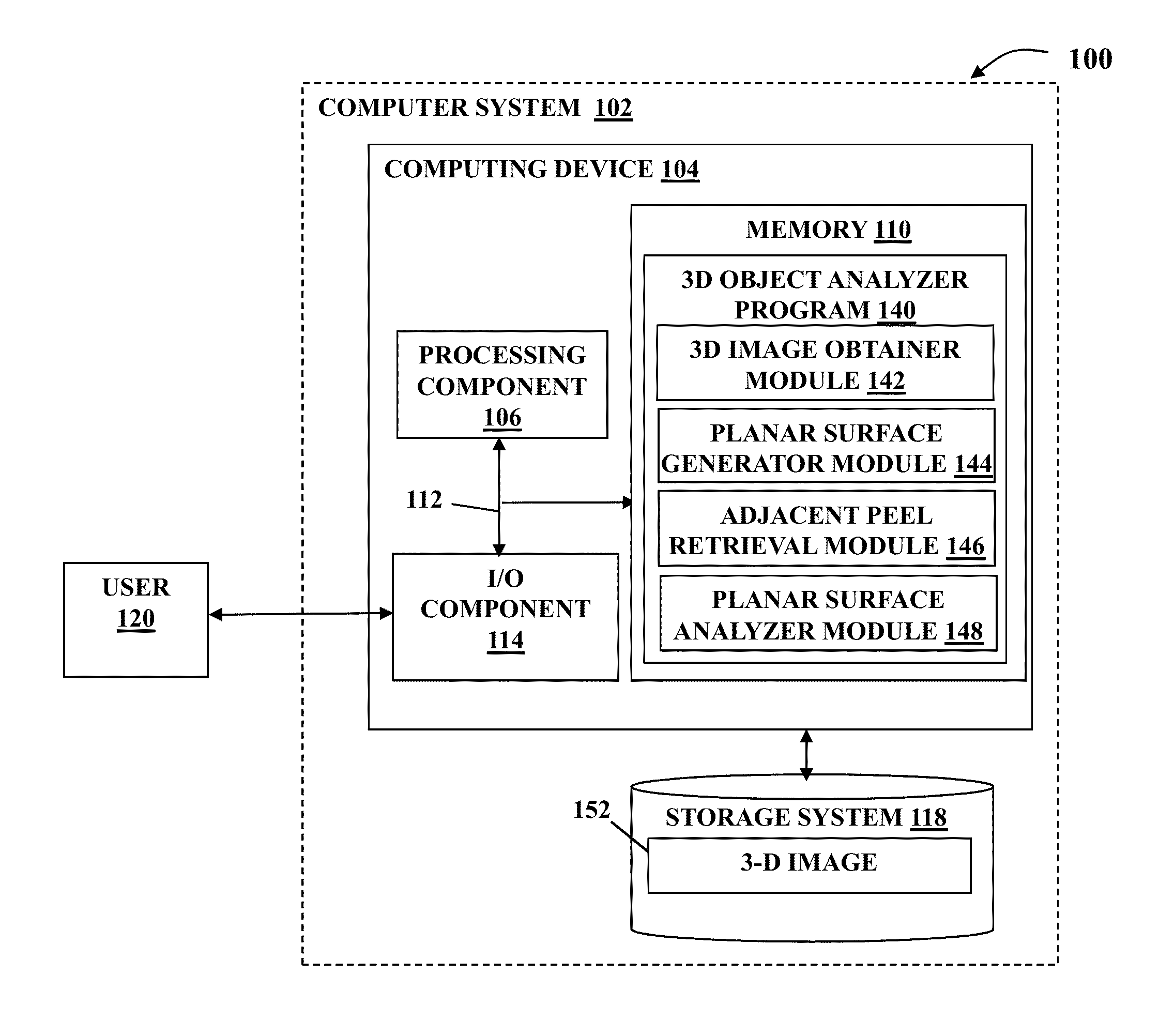
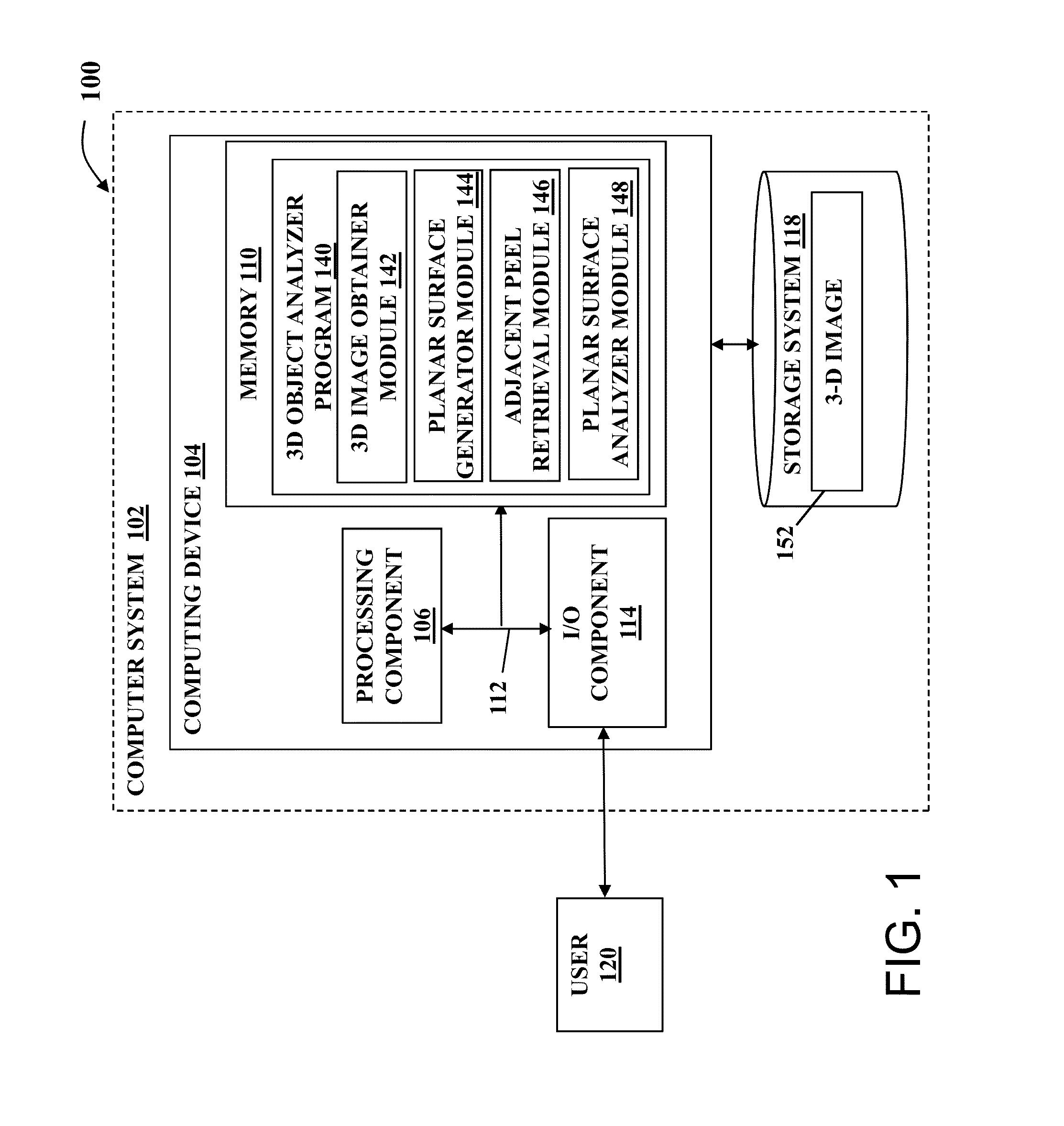
[0020]As indicated above, aspects of the invention provide a solution for analyzing an object, such as a part of a turbo machine. A planar surface is generated using a curved reformat function based on a surface of a three-dimensional (3D) image of an object. A peel of the 3D image that is adjacent to the surface is determined. Based on the peel, a second planar surface is generated. These two, and / or other similarly generated planar surfaces can be analyzed to determine characteristics of the original object.

[0021]Turning to the drawings, FIG. 1 shows an illustrative environment 100 for analyzing a 3D object. To this extent, environment 100 includes a computer system 102 that can perform a process described herein in order to analyze a 3D object. In particular, computer system 102 is shown including a computing device 104 that includes a 3D object analyzer program 140, which makes computing device 104 operable to analyze a 3D object by performing a process described herein.

[0022]Co...


PUM


Abstract

Aspects of the invention provide a solution for analyzing an object, such as a part of a turbo machine. A planar surface is generated using a curved reformat function based on a surface of a three-dimensional (3D) image of an object. A peel of the 3D image that is adjacent to the surface is determined. Based on the peel, a second planar surface is generated. These two, and/or other similarly generated planar surfaces can be analyzed to determine characteristics of the original object.

Description

BACKGROUND OF THE INVENTION[0001]The subject matter disclosed herein relates generally to defect detection. More specifically, the present invention relates to detection of irregularities in a part of a mechanical machine, such as turbo machine part.[0002]In a modern mechanical machine, such as a turbo machine, a plurality of parts work together to perform the machine's function. These parts must be assembled in such a way that all of the parts mesh together correctly. This often requires exact tolerances for such parts elements as part size and / or dimensions and / or the size and / or dimensions of any hole, slot, etc., that is located in the part. A variance in any of these tolerances can cause the part and / or the machine as a whole not to function for its intended purpose. Additionally, or in the alternative, a variance in any of these tolerances can cause a decrease in the lifespan of a machine part. In a high-stress environment, this can lead to an abrupt failure in such a part.[00...

Claims


Application Information

Patent Timeline
IPC IPC(8): G06K9/32
CPCG06K9/3241G01N29/0609G01N29/0645G01N29/069G01N29/11G01N29/226G06T7/0004G06T2207/10081G06T2207/30164
Inventor GEORGE, SHERIGOVINDASAMY, HARIBASKARKULKARNI, UTKARSH MADHAVPOKUTNEV, PAVELROSENMUELLER, MARKOSUPPES, ALEXANDER
Owner BAKER HUGHES INC
Why Eureka
Try Eureka