
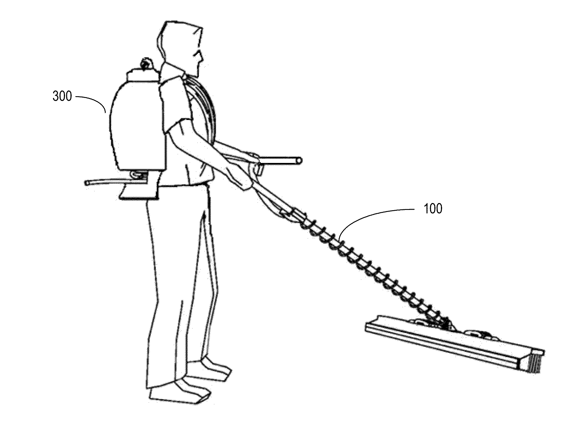
Mechanism for cleaning solar collector surfaces

a solar collector and surface cleaning technology, applied in the direction of carpet cleaners, vehicle cleaning, cleaning using liquids, etc., can solve the problems of increasing the production of carbon dioxide and other gas emissions that are potentially harmful to humans and the environment, and the use of fossil fuels

Active Publication Date: 2014-07-24
NOVASOURCE POWER OPCO INC
View PDF5 Cites 54 Cited by
  • Summary
  • Abstract
  • Description
  • Claims
  • Application Information

AI Technical Summary

Benefits of technology

The patent describes a system for cleaning a solar collector using a robotic cleaning device that can traverse across a row of inclined solar collectors and cross gaps between them. The cleaning device includes a frame, a front continuous track mechanism, a rear continuous track mechanism, and a first and second liquid-dispensing unit, as well as a first and second squeegee element. The system can use a single squeegee or both a brush element and a liquid spray to clean the collector surface. The cleaning head can be positioned in different orientations to reach the collector surface with the squeegee element or the brush element. The technical effects of the patent include improved efficiency and effectiveness in cleaning solar collectors.

Problems solved by technology

However, there are several known drawbacks associated with the use of fossil fuels.
For example, fossil fuels are generally considered to be a nonrenewable source of energy and may become less abundantly available in the foreseeable future.
Also, the burning of fossil fuels typically results in the production of carbon dioxide and other gas emissions that are potentially harmful to humans and the environment.
However, such areas are also prone to high winds and dusty conditions.
Over time, dust and other airborne particulate can accumulate on the collector surface and block light that would otherwise be incident on the collector surface, thereby reducing the potential power output of the solar collector.
However, traditional manual-cleaning techniques, including pressure washing and deluge cleaning, require a substantial supply of water and a significant amount of labor and power resources.
For solar collectors that are installed on rooftops or in remote locations, frequent manual cleaning may not be practical.

Method used


Image

  • Mechanism for cleaning solar collector surfaces
  • Mechanism for cleaning solar collector surfaces
  • Mechanism for cleaning solar collector surfaces

Examples


Embodiment Construction

[0024]The following description is presented to enable a person of ordinary skill in the art to make and use the various embodiments. Descriptions of specific devices, techniques, and applications are provided only as examples. Various modifications to the examples described herein will be readily apparent to those of ordinary skill in the art, and the general principles defined herein may be applied to other examples and applications without departing from the spirit and scope of the various embodiments. Thus, the various embodiments are not intended to be limited to the examples described herein and shown, but are to be accorded the scope consistent with the claims.

[0025]As explained above, dust and other airborne particulate can accumulate on the collector surface of a solar collector and block light that would otherwise be incident on the collector surface. Accumulated particulates and other debris tend to reduce the amount of solar energy available for conversion and thereby re...


PUM


Abstract

A system and method for cleaning a collector surface of a solar collector. The system includes a first liquid-dispensing unit configured to deliver a first spray of liquid to the collector surface. The system also includes a brush element having a longitudinal side oriented along a first direction and disposed adjacent to the first liquid-dispensing unit. A first squeegee element is oriented along the first direction and adjacent to the brush element. The first squeegee element, the brush element, and the first liquid-dispensing unit define a first cleaning area. A second squeegee element is oriented along the first direction and separated from the first squeegee element by a gap to define a second cleaning area. The system also includes a second liquid-dispensing unit configured to deliver a second spray of liquid to the second cleaning area located between the first and second squeegees.

Description

BACKGROUND[0001]1. Field[0002]The present disclosure relates generally to an apparatus and method for cleaning solar collectors and, more specifically, to a brush and squeegee mechanism for removing dust sediment from the collector surface of a solar collector.[0003]2. Description of Related Art[0004]Traditionally, fossil fuels, including coal, oil, and natural gas, have been used to supply electrical energy for residential and commercial purposes. Presently, fossil fuels are an abundant and relatively inexpensive source of energy. However, there are several known drawbacks associated with the use of fossil fuels. For example, fossil fuels are generally considered to be a nonrenewable source of energy and may become less abundantly available in the foreseeable future. Also, the burning of fossil fuels typically results in the production of carbon dioxide and other gas emissions that are potentially harmful to humans and the environment.[0005]Harnessing light energy from the sun is o...

Claims


Application Information

Patent Timeline
IPC IPC(8): B08B1/00A47L7/00
CPCA47L7/0004B08B1/00F24S40/20A47L11/38B08B3/026B08B1/12Y02E10/40Y02E10/52
Inventor GROSSMAN, MARCJEANTY, CEDRIC
Owner NOVASOURCE POWER OPCO INC
Learn More