Quasi self-destructive core for investment casting

a self-destructive core and core technology, applied in the field of investment casting, can solve the problems of limited investment casting, difficult removal or destruction of ceramic cores used in csic without affecting the molded part, and severe restrictions on the use of csi

Inactive Publication Date: 2014-07-24
SIKORSKY AIRCRAFT CORP
View PDF4 Cites 17 Cited by
  • Summary
  • Abstract
  • Description
  • Claims
  • Application Information

AI Technical Summary

Problems solved by technology

However, investment casting is limited by the design of passages within the mold.
Unlike a sand core used in a sand casting process, the ceramic cores used in CSIC are difficult to remove or destroy without affecting the molded part.
As a result, the process of designing passages severely restricts the use of CSIC for applications requiring complex cored passages.

Method used


Image

  • Quasi self-destructive core for investment casting
  • Quasi self-destructive core for investment casting
  • Quasi self-destructive core for investment casting

Examples


Embodiment Construction

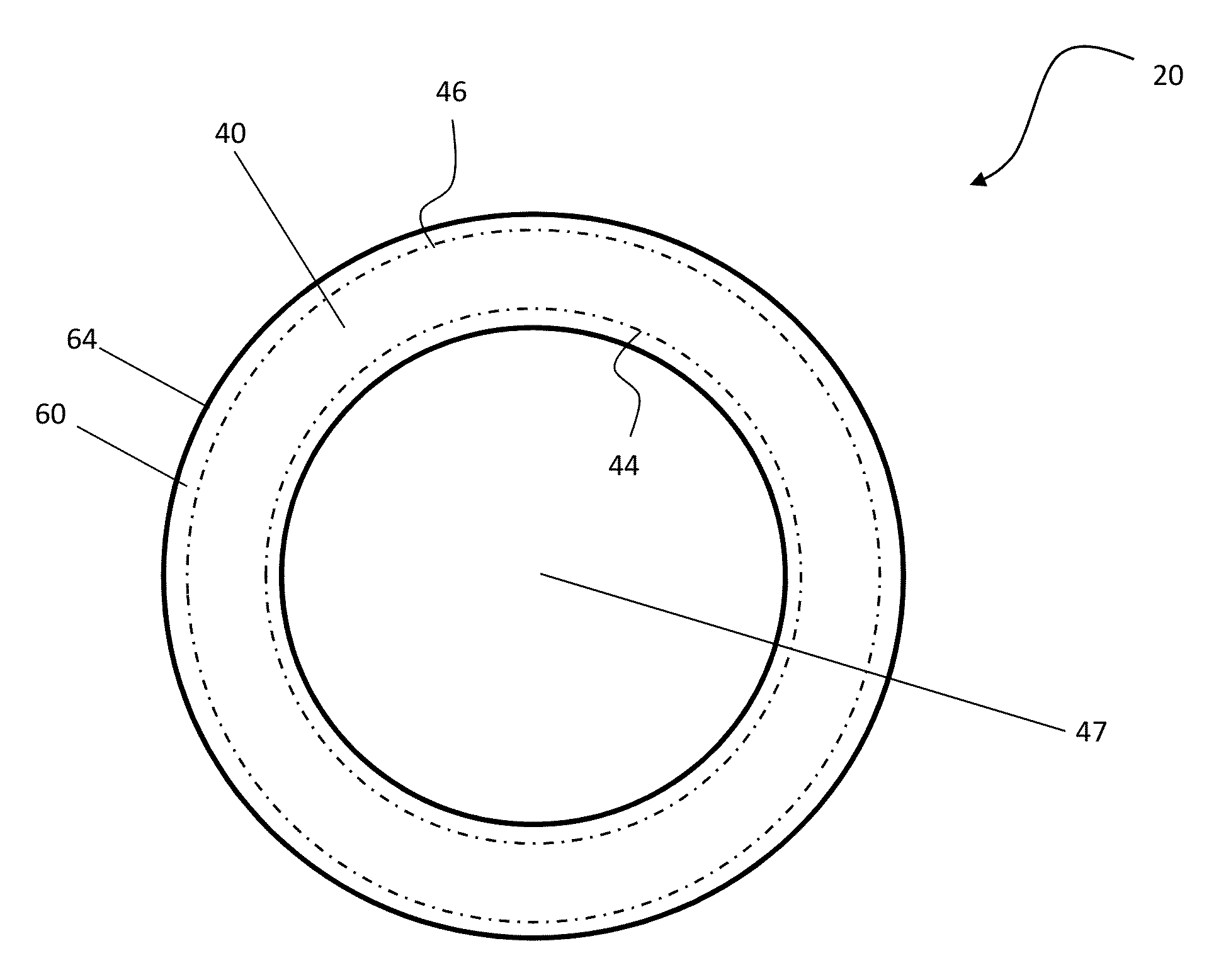
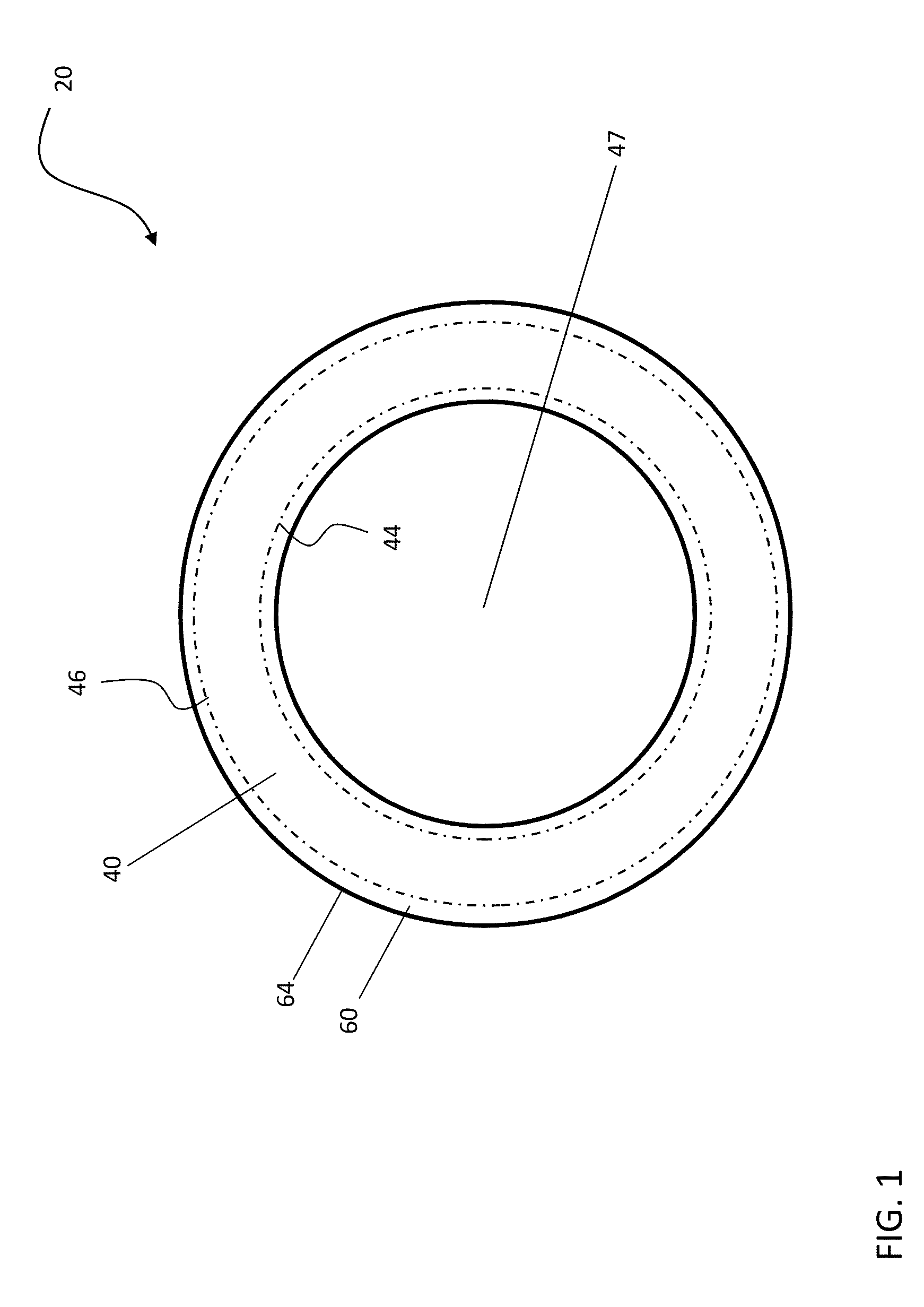
[0015]With reference now to FIG. 1, a cross-section of a composite core 20 for forming a passage in an investment casting mold is illustrated. When inserted into a mold (not shown), the composite core 20 includes a generally hollow structural element 40 and a shell element 60 arranged about the exterior 46 of the structural element 40. The structural element 40 is configured to deform, and therefore break the shell element 60 coupled thereto, when a force is applied to an end 42 (FIG. 2) of the structural element 40.

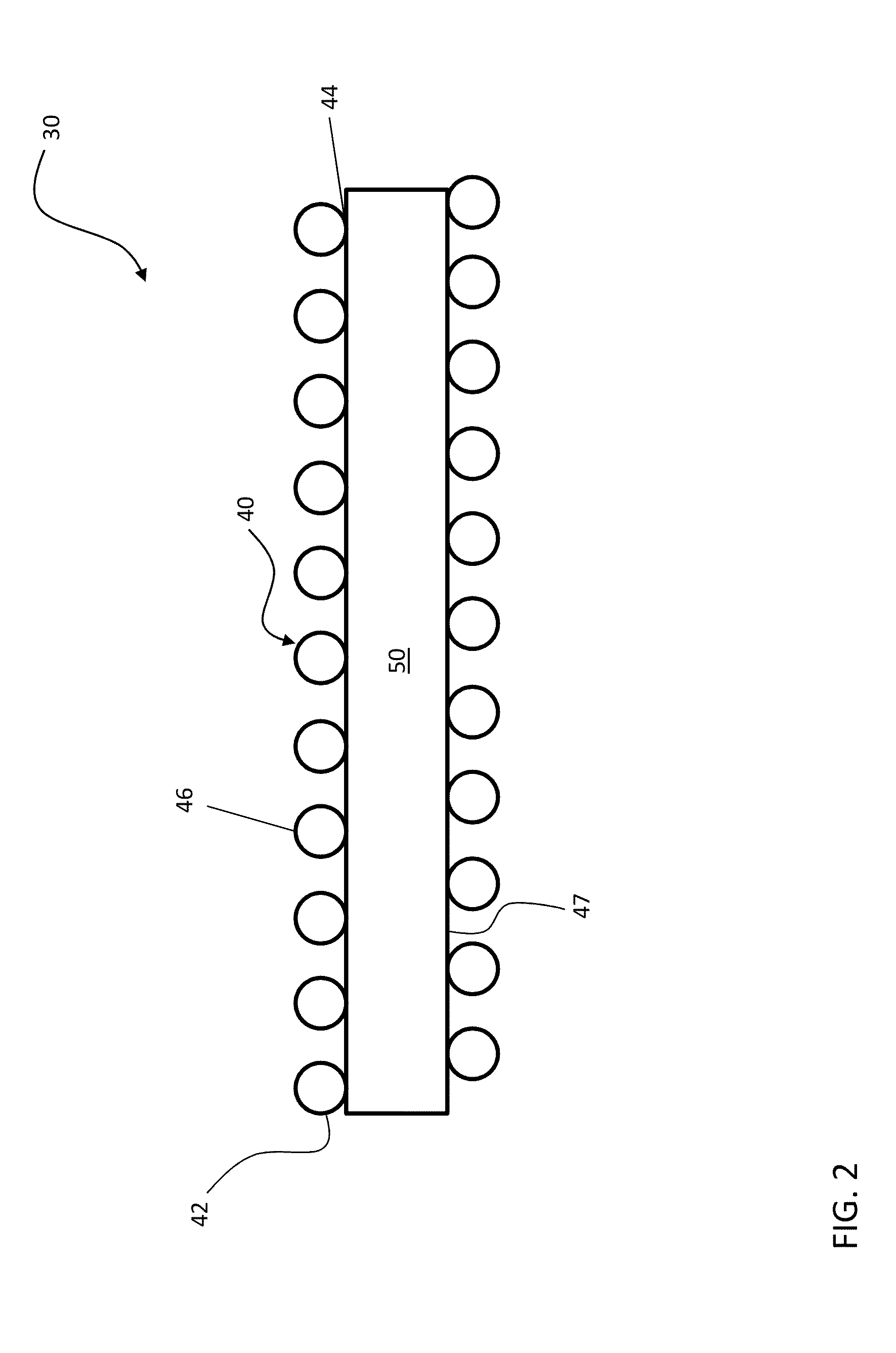
[0016]The composite core 20 is formed using a preform 30, illustrated in more detail in FIG. 2. The preform 30 includes the generally hollow structural element 40 as well as a core element 50 positioned adjacent the interior surface 44 of the structural element. The structural element 40 may be pre-formed and the core element 50 inserted into the hollow center 47 of the structural element 40, or alternatively, the structural element 40 may be formed around the exterior o...


PUM

PropertyMeasurementUnit
forceaaaaaaaaaa
sizesaaaaaaaaaa
sizeaaaaaaaaaa

Abstract

A composite core for forming a passage in an investment casting mold is provided including a generally hollow structural element. The structural element is configured to deform when a force is applied to an end thereof. A rigid shell element is formed about the structural element. The shell element extends beyond both an interior surface and an exterior surface of the structural element. The shell element is configured to shatter when the structural element deforms.

Description

This invention was made with Government support under N00019-06-C-0081 awarded by the Department of the Navy. The Government has certain rights in this invention.BACKGROUND OF THE INVENTION[0001]Exemplary embodiments of the invention generally relate to investment casting, and more particularly, to a core for forming a passage in an investment casting mold.[0002]Investment casting is a commonly used technique for forming metallic components having complex shapes and geometries, especially hollow components such as those used in aerospace applications for example. The production of an investment cast part generally involves producing a ceramic casting mold having an outer ceramic shell with an inside surface corresponding to the shape of the part, and one or more ceramic cores positioned within the outer ceramic shell, corresponding to interior passages to he formed within the part, Molten alloy is introduced into the ceramic casting mold and is then allowed to cool and to harden. Th...

Claims


Application Information

Patent Timeline
Patent Type & Authority Applications(United States)
IPC IPC(8): B22C9/10
CPCB22C9/10
Inventor SONG, SHIHONG G.GIAMPAPA, JAMES S.MEESON, JR., JOHN H.
Owner SIKORSKY AIRCRAFT CORP
Why Eureka
Try Eureka