[0008]The present invention is part of an entirely new regiment for investment
casting. As described and claimed herein, a flexible wax pattern mold may be formed as a
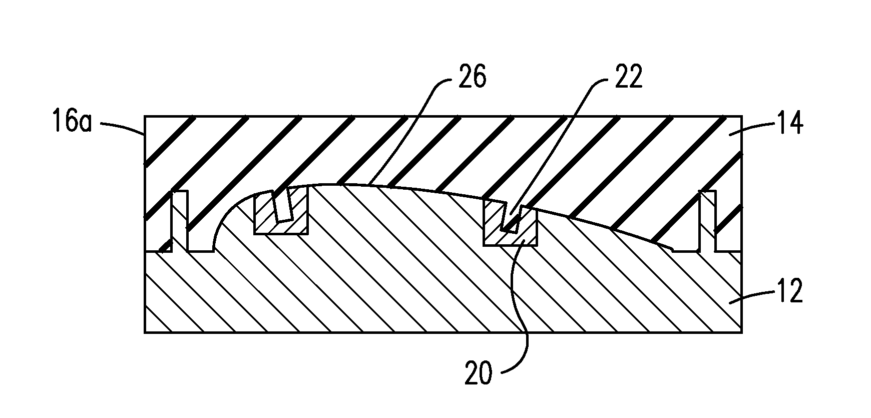
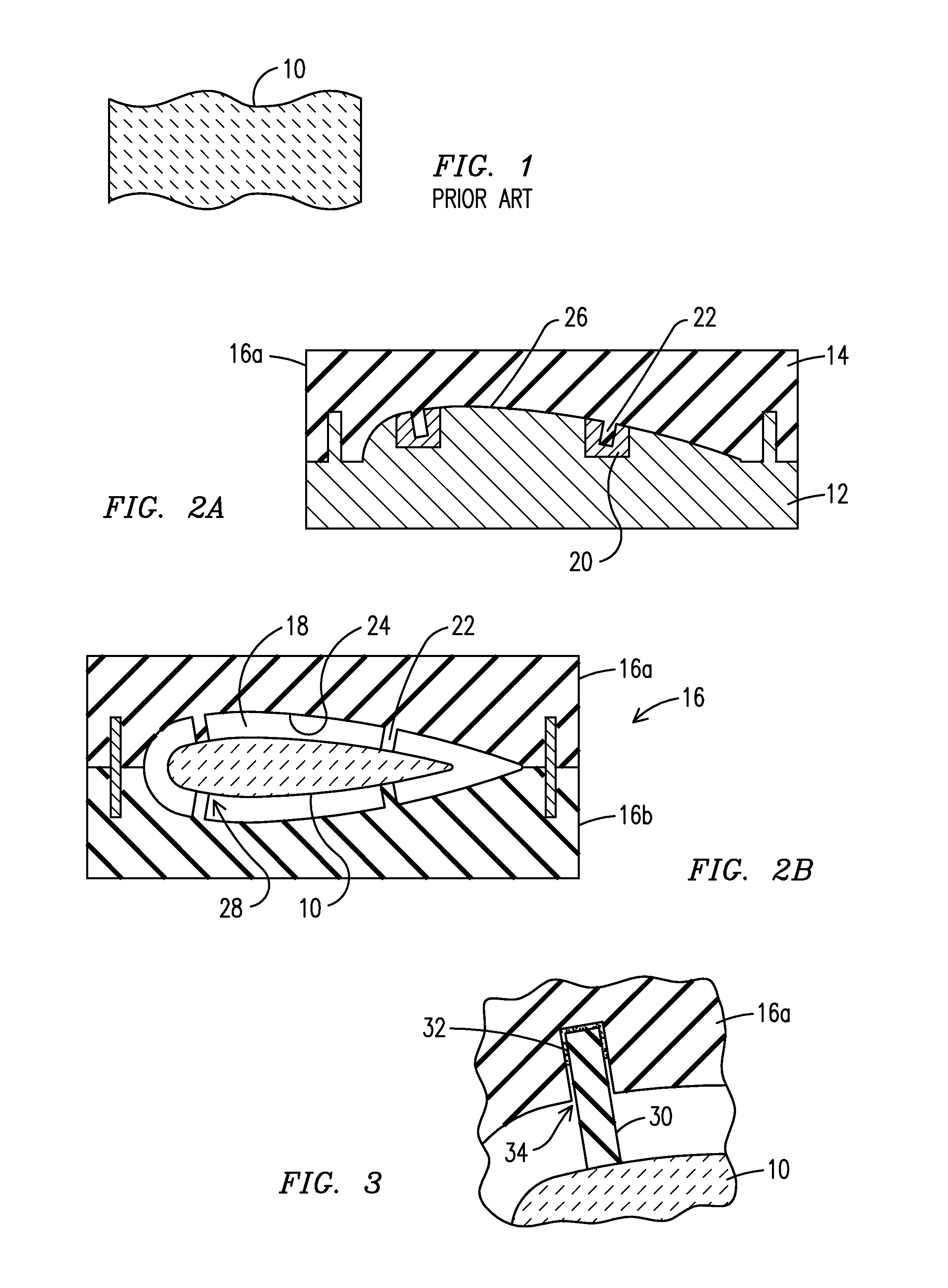
hybrid tool having a flexible insert within a coffin mold. The flexible insert facilitates the removal of the wax pattern tool from the cast wax pattern by deforming the flexible insert around cast features that would otherwise require multiple pull planes for hard tooling. The flexible insert may be cast from a master tool that is machined from a relatively low cost, low
hardness material such as aluminum or mild steel.
[0010]A
ceramic insert placed into the flexible wax pattern mold may also be used to define surface-opening passages in the subsequently cast
metal part, such as
trailing edge cooling holes for a gas
turbine blade. In this embodiment, the ceramic insert would include projections corresponding to a desired shape of the cooling holes. The projections would extend to make contact with the ceramic core, thereby defining cooling channels in the subsequently cast part that extend from a hollow interior portion of the blade (defined by the ceramic core) to the blade surface (defined by the inside surface of the ceramic shell). The distal end of the projection may be formed with a feature that mates with a cooperating feature formed on the ceramic core. Mechanical contact between the core and the ceramic insert projection serves to precisely locate the ceramic core within the flexible wax pattern mold and also to mechanically support the ceramic core during the subsequent wax and metal injection steps.
[0011]The flexible insert of the wax pattern mold may be formed to include alignment features that allow the insert to be precisely located relative to the surrounding coffin mold, which in turn, can precisely locate the insert and any feature formed on the insert relative to the enclosed ceramic core for the wax injection step.
[0012]The molding material used to form the flexible mold or flexible mold insert may be infused with or cast around a material or device which allows the flexible insert to react in a desired way; broadly described herein as the flexible insert containing a reactive element. The reactive element may be a filler material which imparts a desired characteristic to the subsequently cured material. For example, if magnetic particles are used as filler, the cured flexible insert will be responsive to
magnetic energy. This characteristic may be useful for securing the flexible insert within the surrounding coffin mold when the coffin mold is formed to include permanent or electromagnets. If thermally conductive or thermally insulating materials are used as filler,
heat transfer through the flexible insert may be more conveniently controlled during its use.
[0014]Positioning pins (wires) may be used with a flexible wax pattern mold to mechanically support the enclosed ceramic core during metal
casting, and importantly, these may be positioned against the ceramic core prior to the wax injection step. Specialized pin supporting elements are located into recesses in the surface of the flexible insert, thereby precisely positioning the pins relative to the ceramic core prior to wax injection. This allows the pins to support the core during wax injection and it also allows the pins to be located with more precision than in the prior art process which required the pins to be inserted through the already-cast wax pattern. As a result, damage to the fragile ceramic core is reduced and process yield is increased.
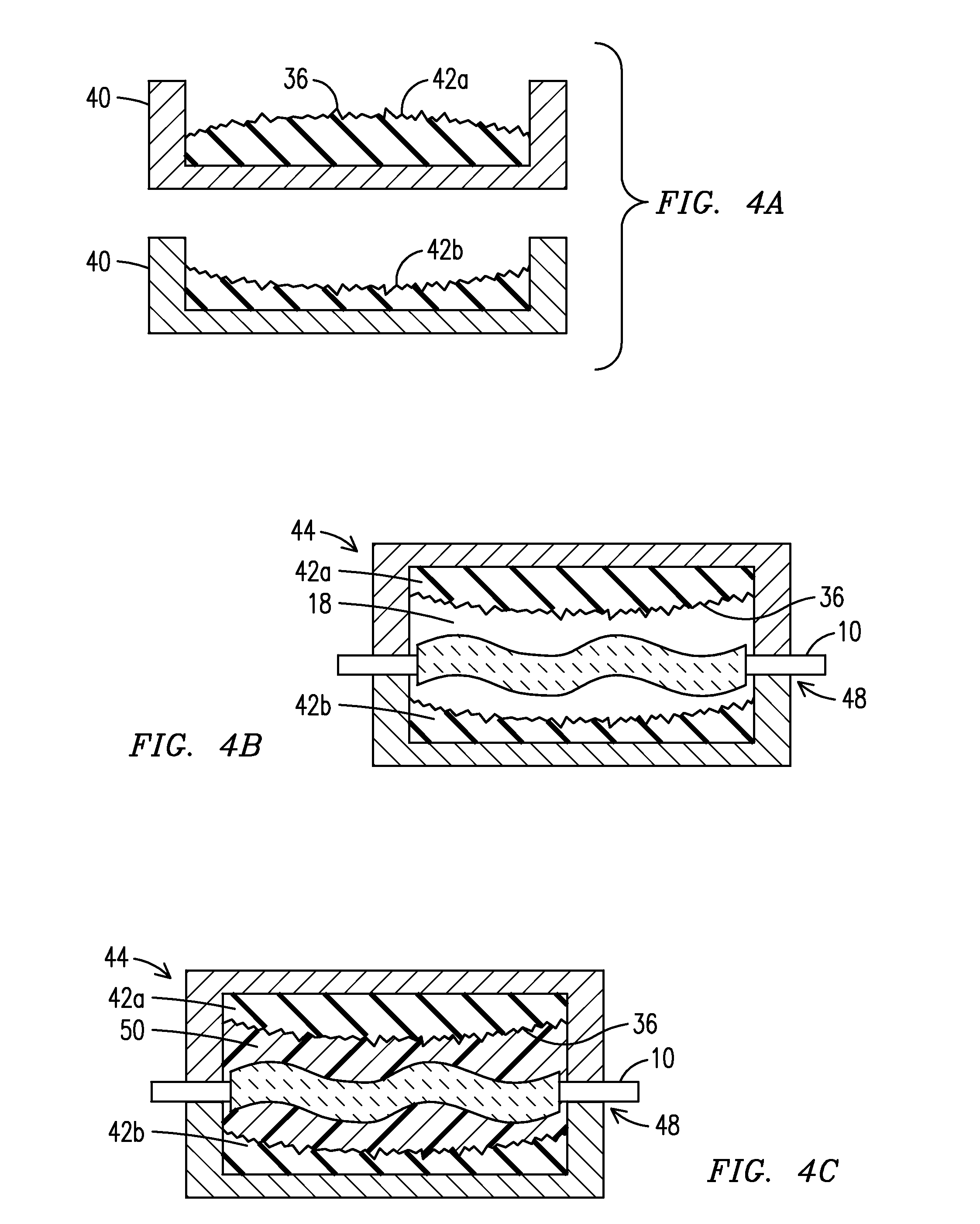
[0015]An enabling technology which is exploited in the present invention is described in U.S. Pat. Nos. 7,141,812 and 7,410,606 and 7,411,204, all assigned to Mikro Systems, Inc. of Charlottesville, Va., and incorporated by reference herein. This technology is commonly referred to as Tomo Lithographic Molding Technology (hereinafter referred to as the “Tomo process”), and it involves the use of a
metallic foil stack lamination mold to produce a flexible derived mold, which in turn is then used to cast a component part. The component design is first embodied in a digital model and is then digitally sliced, and a
metal foil is formed corresponding to each slice using
photolithography or other precision
material removal process. The inherent precision of the two-dimensional
material removal process in combination with the designer's ability to control the thickness of the various slices in the third dimension provides a degree of three-dimensional manufacturing tolerance precision that was not previously available using standard mold
machining processes. The foils are stacked together to form a lamination mold for receiving suitable flexible molding material. The term “flexible” is used herein to refer to a material such as a
room temperature vulcanizing (RTV)
silicon rubber or other material which can be used to form a “flexible mold” which is not rigid like prior art metal molds, but that allows the mold to be bent and stretched to a degree in order to facilitate the removal of the mold from a structure cast therein. Furthermore, the terms “flexible mold” and “flexible tool” may be used herein to include a self-standing flexible structure as well as a flexible liner or insert contained within a rigid coffin mold. A component is then cast directly into the flexible mold. The flexibility of the mold material enables the casting of component features having protruding undercuts and reverse cross-section tapers due to the ability of the flexible mold material to deform around the feature as the cast part is pulled out of the mold.


