Method of making injection molding cooled thread split inserts

a technology of cooled thread and split inserts, which is applied in the field of making pairs of cooled thread split inserts, can solve the problems of time-consuming and therefore relatively costly problems

Inactive Publication Date: 2004-01-27
MOLD MASTERS 2007
View PDF7 Cites 47 Cited by
  • Summary
  • Abstract
  • Description
  • Claims
  • Application Information

AI Technical Summary

Problems solved by technology

This method has the disadvantage that both parts must be machined to provide cooli...

Method used


Image

  • Method of making injection molding cooled thread split inserts
  • Method of making injection molding cooled thread split inserts
  • Method of making injection molding cooled thread split inserts

Examples


Embodiment Construction

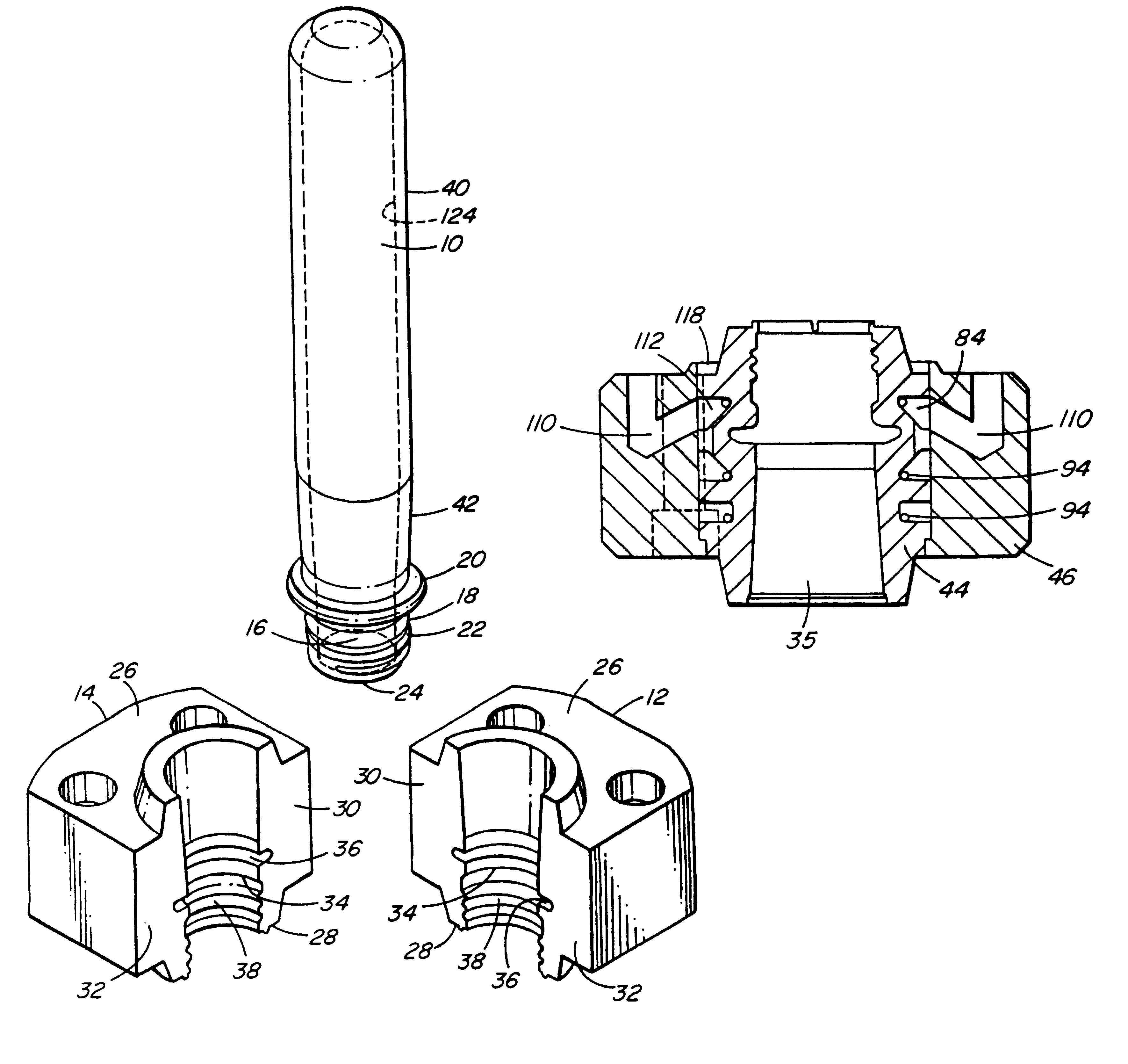
Reference is first made to FIG. 1 which shows a bottle preform 10 and a pair of thread split inserts 12, 14 made according to a preferred embodiment of the invention. As can be seen, the bottle preform 10 is hollow and is elongated to a selected length. The bottle preform 10 has a neck portion 16 with an outer surface 18 forming a ring collar 20 and threads 22 extending between an open end 24 and the ring collar 20. The bottle preform 10 is injection molded of polyethylene terephthalate (PET) according to a conventional injection molding cycle in a conventional mold.

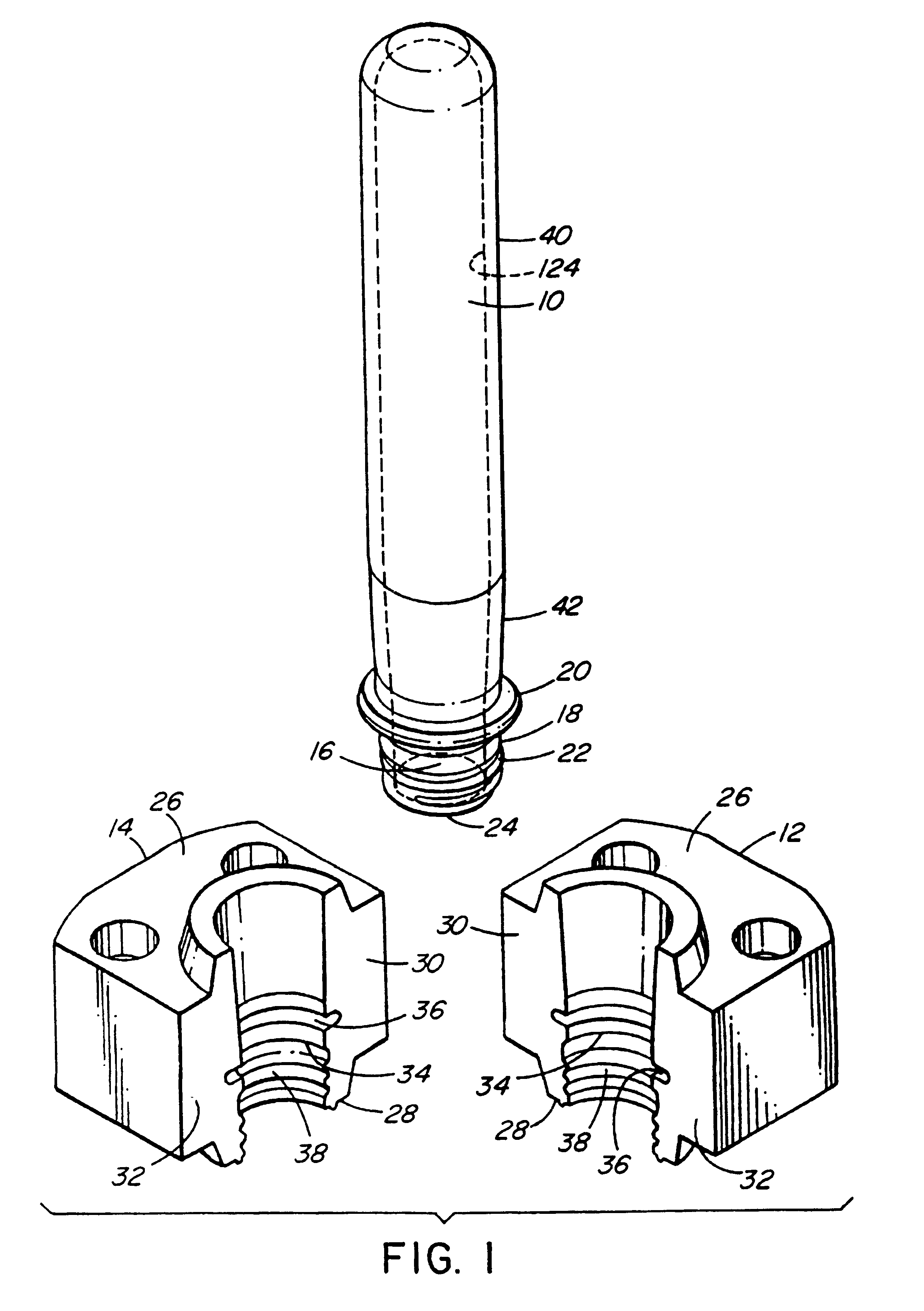
Each thread split insert 12, 14 has a front end 26, a rear end 28 and flat inner aligned faces 30, 32 extending on opposite sides of a curved inner surface 34. During molding of the bottled preforms 10, the thread split inserts 12, 14 are mounted in a mold with the respective flat inner faces 30, 32 of the thread split inserts 12, 14 abutting, whereby as seen in FIG. 13 the curved inner surfaces 34 of the thread split in...


PUM

PropertyMeasurementUnit
Sizeaaaaaaaaaa
Shapeaaaaaaaaaa

Abstract

A method of making pairs of thread splits inserts used to injection mold bottle preforms. Machining a hollow outer part of the pair of thread split inserts with an opening therethrough and outer portions of two cooling conduits extending from the opening therethrough to respective inlets and outlets. Making an inner part of the pair of thread split inserts by injection molding a ceramic core with the required shape and investment casting the inner part around the ceramic core. The outer surface of the inner part having grooves to partially form inner portions of the two cooling fluid conduits. Then machining the cast inner part to fit in the opening through the outer part. Mounting the outer part around the inner part with the inner and outer portions of the two cooling fluid conduits aligned. Applying brazing material between the inner and outer parts and heating them in a vacuum furnace to integrally braze them together. Finally, cutting the integral inner and outer parts in half to form the pair of thread split inserts with each of the thread split inserts having one of the cooling fluid conduits therein.

Description

BACKGROUND OF THE INVENTIONThis invention relates a method of making pairs of cooled thread split inserts used to injection mold bottle preforms.As seen in the applicant's U.S. Pat. No. 5,599,567 which issued Feb. 4, 1997, it is well known to use a pair of thread split inserts in a mold to form the threaded neck portion of a PET bottled preform. The neck portion of the preform also has a ring collar which is used to eject the preform from the mold. The thread split inserts have conduits through which cooling fluid is circulated to cool the neck portion of the preform prior to ejection.In the past, thread split inserts have been made by machining steel upper and lower parts and then integrally brazing them together. This method has the disadvantage that both parts must be machined to provide cooling fluid conduits and threads and this is time consuming and therefore relatively costly.SUMMARY OF THE INVENTIONAccordingly, it is an object of the present invention to at least partially o...

Claims


Application Information

Patent Timeline
IPC IPC(8): B23P15/00B23P15/24B29C33/04B29C33/38B29C45/33B29C45/73
CPCB23P15/007B23P15/24B29C33/04B29C45/7312B29C45/33Y10T29/49787B29C2033/042Y10T29/49794Y10T29/49796Y10T29/49989
Inventor GELLERT, JOBST ULRICH
Owner MOLD MASTERS 2007
Why Eureka
Try Eureka