Power supply apparatus, control method thereof, and power supply system

Inactive Publication Date: 2014-07-24
CANON KK
View PDF4 Cites 8 Cited by
  • Summary
  • Abstract
  • Description
  • Claims
  • Application Information

AI Technical Summary

Benefits of technology

[0009]The present invention has been made in consideration of the aforementioned problems and realizes a technique of controlling power to b

Problems solved by technology

In this case, a failure may occur in the IC card.
In the conventional power receiving apparatus, however, the excessive power is continuously supplied from the power supply apparatus to the IC card during the time after excessive power supply from the power supply apparatus has started until the inte

Method used


Image

  • Power supply apparatus, control method thereof, and power supply system
  • Power supply apparatus, control method thereof, and power supply system
  • Power supply apparatus, control method thereof, and power supply system

Examples


Example

[0021]The present invention will now be described using the first embodiment as an example. Note that the present invention is not limited to the first embodiment.

First Embodiment

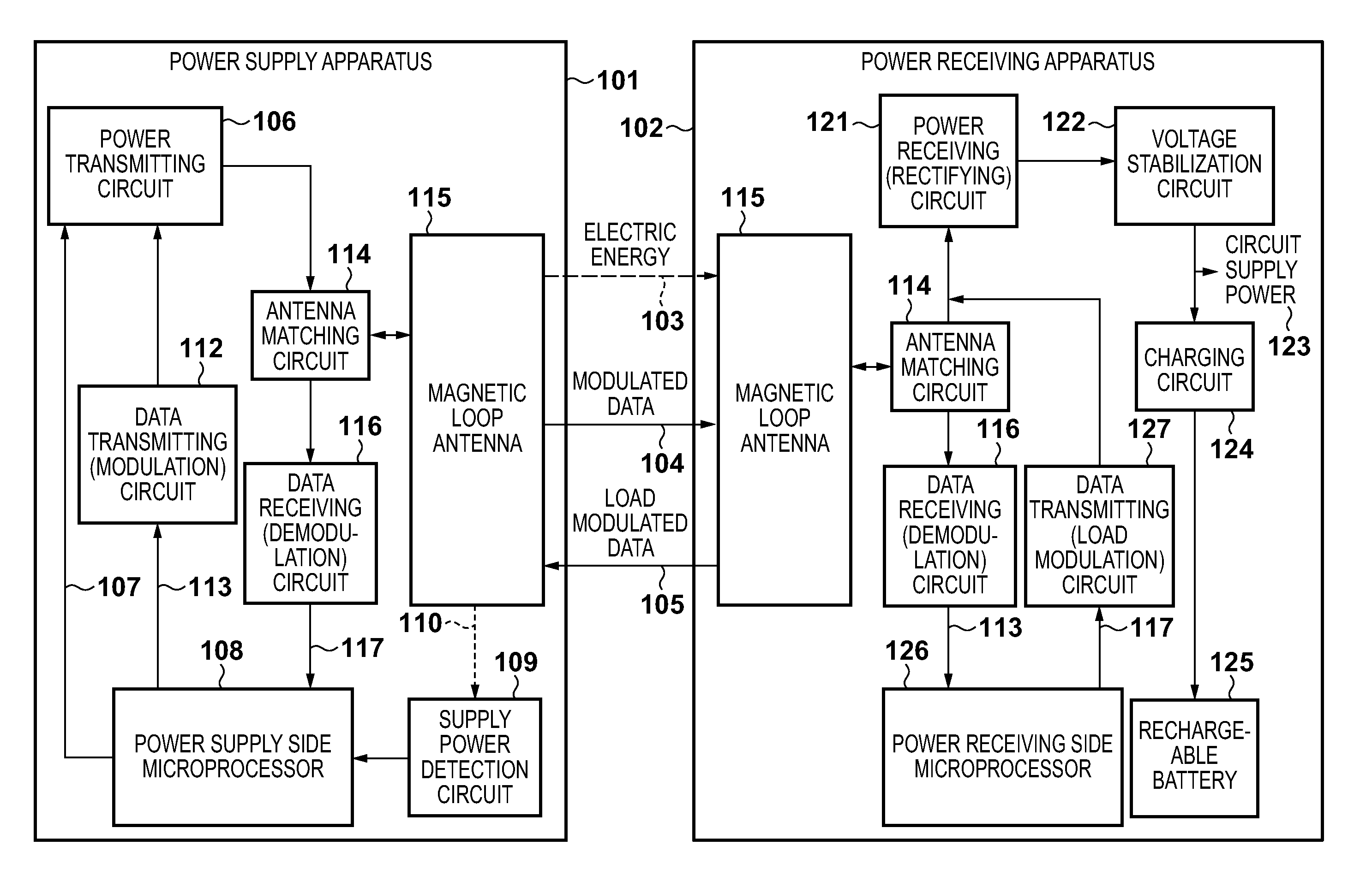
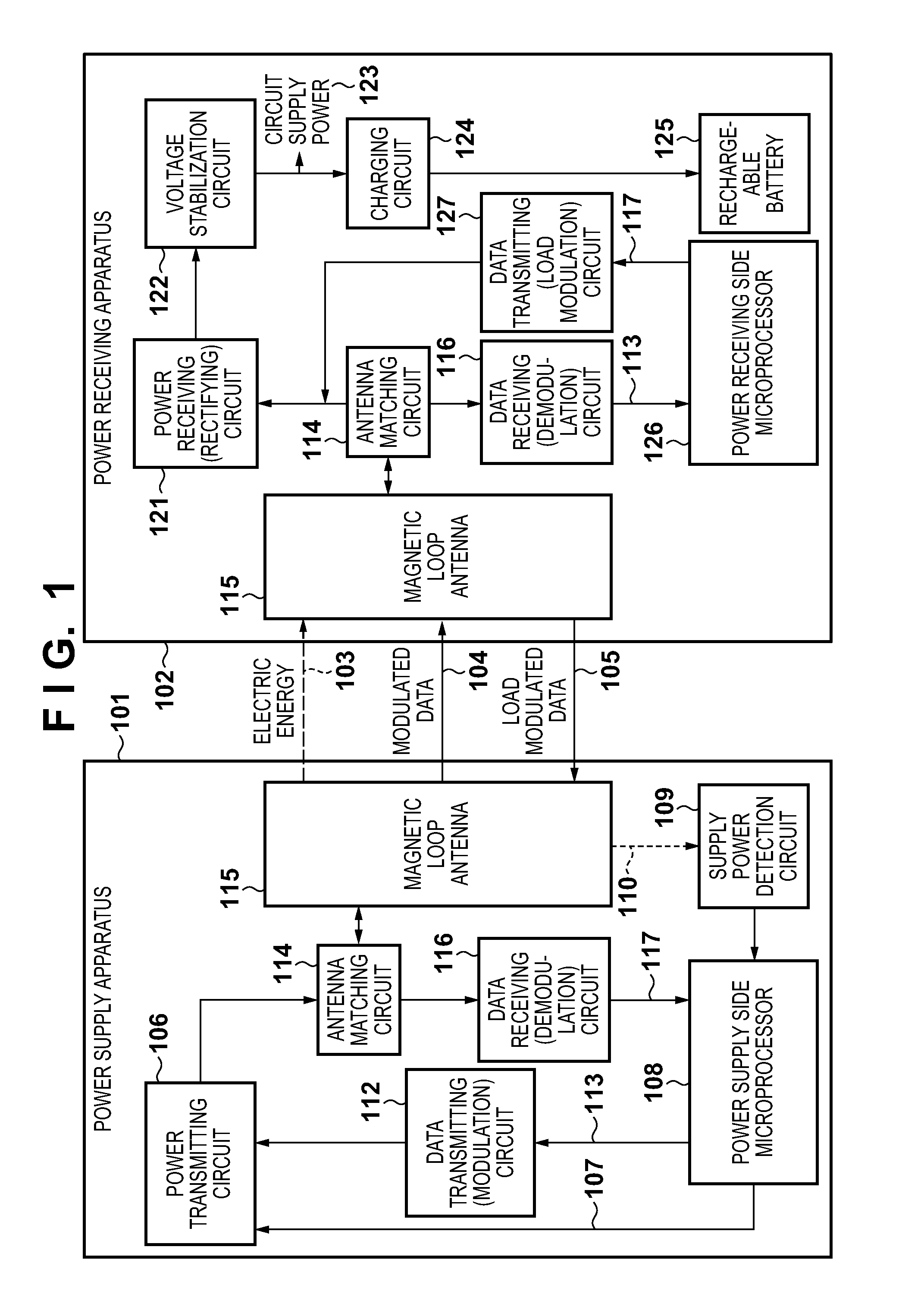
[0022]FIG. 1 shows a power supply system according to the first embodiment. The power supply system according to the first embodiment will be described below with reference to FIG. 1.

[0023]Referring to FIG. 1, a power supply apparatus 101 wirelessly supplies power to a power receiving apparatus 102. Between the power supply apparatus 101 and the power receiving apparatus 102, the power supply apparatus 101 performs one-way or bidirectional data communication with the power receiving apparatus 102. The power supply apparatus 101 starts power supply to the power receiving apparatus 102 after authenticating it. Transmission power generated by a power transmitting circuit 106 passes through an antenna matching circuit 114, and is converted into electric energy 103 via a magnetic loop antenna 115 and emitted in...


PUM


Abstract

A power supply apparatus comprises a power supply unit which wirelessly supplies power; a communication unit which transmits a predetermined instruction to request transmission of identification information; and a control unit which, when the predetermined instruction is transmitted to a predetermined device, controls to transmit the identification information of the predetermined device to the power supply apparatus after a first time elapses, wherein when the predetermined instruction is transmitted to a power receiving apparatus different from the predetermined device, the control unit controls to transmit the identification information of the power receiving apparatus to the power supply apparatus after a second time longer than the first time elapses.

Description

BACKGROUND OF THE INVENTION[0001]1. Field of the Invention[0002]The present invention relates to a power supply apparatus that controls power to be wirelessly supplied to a power receiving apparatus, and a power supply system.[0003]2. Description of the Related Art[0004]There is known a wireless power supply system including a power receiving apparatus and a power supply apparatus that wirelessly supplies power to the power receiving apparatus without intervening a connector or a cable. As an example of such a noncontact power supply system, a system is known, which magnetically couples a power supply apparatus and a power receiving apparatus in accordance with a specific frequency and causes the power supply apparatus to transmit power to the power receiving apparatus by magnetic resonance. In this case, the power supply apparatus controls the power to be supplied to the power receiving apparatus by magnetic resonance in accordance with power acceptable by the power receiving appar...

Claims


Application Information

Patent Timeline
IPC IPC(8): H04B5/00H02J7/02H02J7/00H01F38/14
CPCH02J7/025H04B5/0037H04B5/0031H02J50/10H02J7/00045H02J7/00036H02J7/00047H02J50/80H02J50/12
Inventor ADACHI, YUKIHIRO
Owner CANON KK
Why Eureka
Try Eureka