
Display panel and display device including the same

a display panel and display panel technology, applied in the field of display devices, can solve the problems of limited thickness minimization of related art display devices obtained up to now, and achieve the effect of preventing light leakag

Active Publication Date: 2014-07-24
LG DISPLAY CO LTD
View PDF16 Cites 40 Cited by
  • Summary
  • Abstract
  • Description
  • Claims
  • Application Information

AI Technical Summary

Benefits of technology

The technical effect of this patent is to provide a display panel that protects the substrate from external environments and prevents light leakage. This results in a better display device that is more durable and reliable.

Problems solved by technology

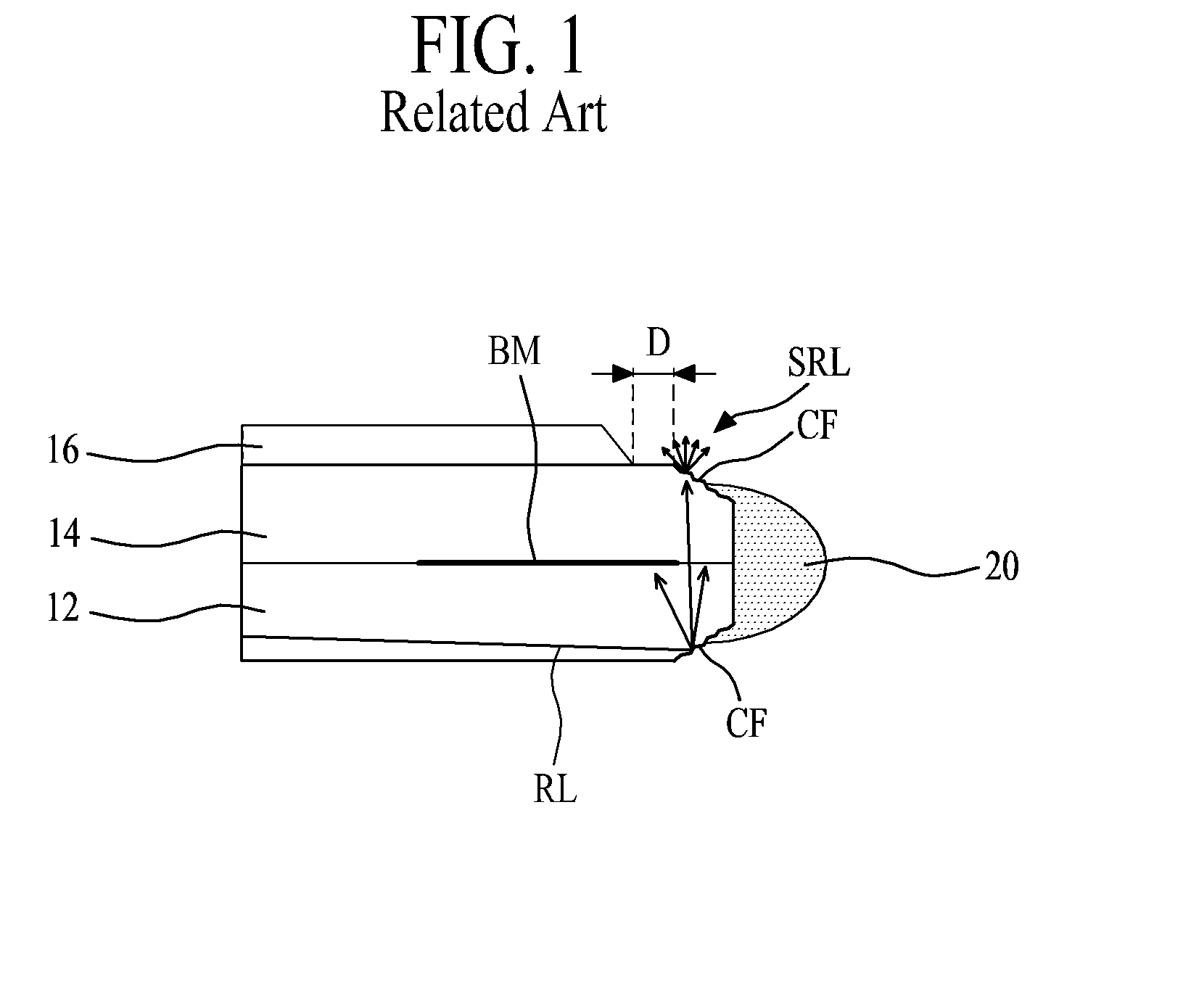
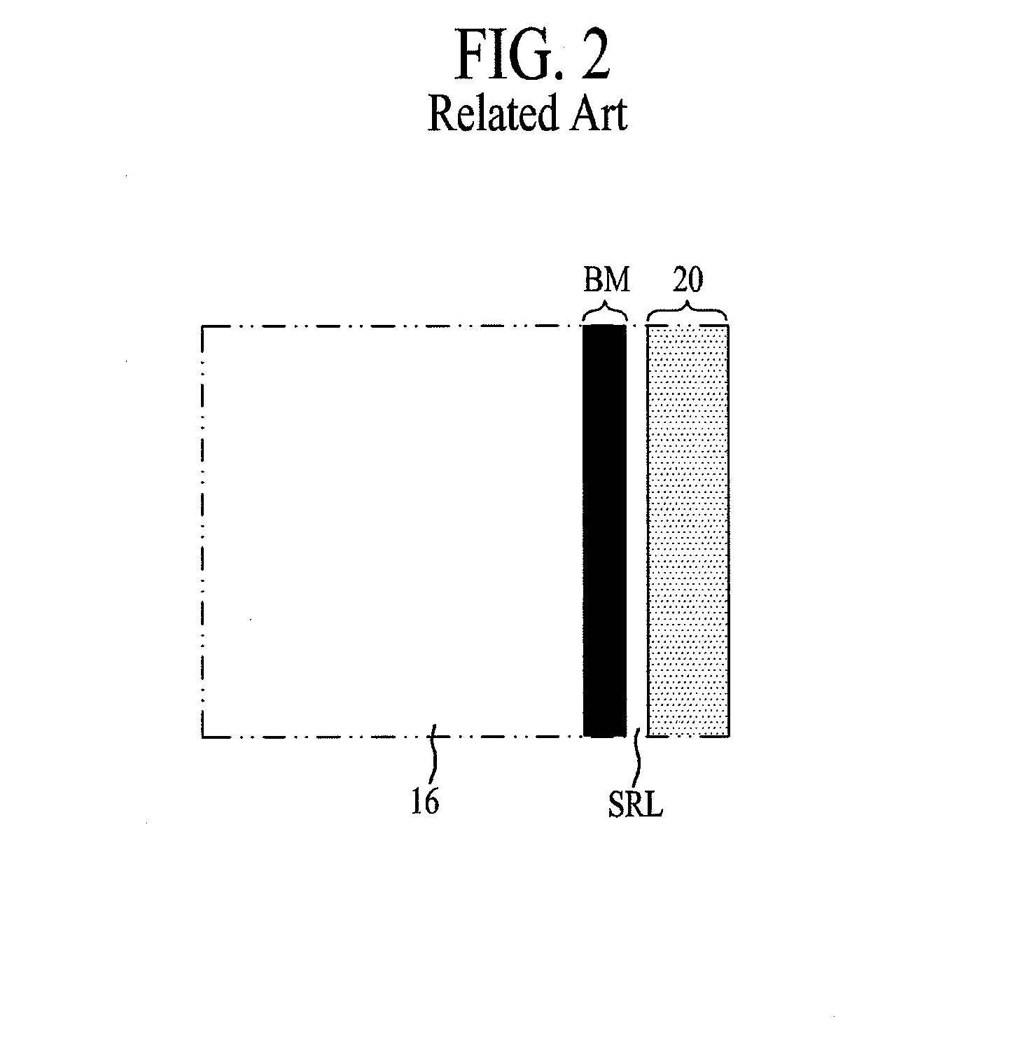
However, the related art display device obtained up to now has limitations in the minimization of thickness and the improvement of exterior appearance due to its structural properties.

Method used


Image

  • Display panel and display device including the same
  • Display panel and display device including the same
  • Display panel and display device including the same

Examples


first embodiment

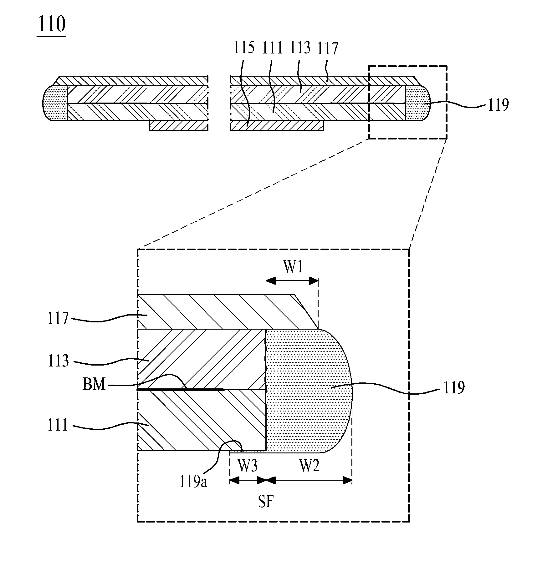
[0045]FIG. 3 is a cross sectional view illustrating a display panel according to the present invention.

[0046]Referring to FIG. 3, the display panel 110 according to the first embodiment of the present invention may include a lower substrate 111, an upper substrate 113 disposed on the lower substrate 111, an upper polarizing film 117 attached to an entire upper surface of the upper substrate 113, and a panel protection member 119 for covering the side faces of the lower substrate 111 and upper substrate 113. The upper polarizing film 117 is an example of an optical sheet or optical film. At this time, in this example, the lower substrate 111 and the upper substrate 113 confronting each other are bonded to each other with a liquid crystal layer interposed therebetween; however, the invention is not limited to thereto and the display panel 100 can be of other types. Also, the size of the upper polarizing film 117 is larger than the size of the upper substrate 113 so that the upper pola...

second embodiment

[0062]FIG. 4 is a cross sectional view illustrating a display panel according to the present invention, which includes an additionally-provided 3-dimensional image optical member. Hereinafter, since the display panel of FIG. 4 is the same as the display panel of FIG. 3, except for the addition of a 3-dimensional image optical member 118, the description thereof is minimized for the sake of brevity, and only the 3-dimensional image optical member 118 will be described in detail as follows.

[0063]The 3-dimensional image optical member 118 is formed on the entire upper surface of the upper polarizing film 117 so that the 3-dimensional image optical member 118 is directly disposed under the panel protection member 119, to thereby display 3-dimensional images according to light transmitting through the upper polarizing film 117. In this case, on the basis of a 3-dimensional image display mode of the display device having the display panel 110 of FIG. 4, an image seen through the left eye ...


PUM

PropertyMeasurementUnit
widthaaaaaaaaaa
widthaaaaaaaaaa
widthaaaaaaaaaa

Abstract

Discussed is a display panel capable of preventing a substrate from being directly exposed to the external and preventing a light leakage. The display panel according to an embodiment includes a lower substrate and an upper substrate coupled to each other and configured to display images; an optical film attached to an upper surface of the upper substrate; and a panel protection member for covering side faces of the lower and upper substrates, wherein at least one side of the optical film extends beyond a side face of at least one side of the upper substrate.

Description

CROSS REFERENCE TO RELATED APPLICATIONS[0001]This application claims the benefit of the Korean Patent Application No. 10-2013-0007860 filed on Jan. 24, 2013, which is hereby incorporated by reference as if fully set forth herein.BACKGROUND OF THE INVENTION[0002]1. Field of the Invention[0003]Embodiments of the present invention relate to a display device, and more particularly, to a display panel which is capable of preventing a substrate from being directly exposed to the external environment, and also preventing a light leakage, and to a display device including the display panel.[0004]2. Discussion of the Related Art[0005]Various display devices, which substitute for CRTs (Cathode Ray Tubes) manufactured in an early stage of display device, have been researched and studied, and examples of such display devices may be liquid crystal display device, plasma display panel, organic light emitting display device, etc.[0006]These display devices are able to achieve a large size by decre...

Claims


Application Information

Patent Timeline
Patent Type & Authority Applications(United States)
IPC IPC(8): G02F1/1339G02F1/1335
CPCG02F1/133528G02F1/1339G02F1/133351G02F2201/50G02F1/133562G02F1/1333G09F9/00G02F1/133308
Inventor KIM, YONG SUNGHAN, SANG HWA
Owner LG DISPLAY CO LTD
Learn More