Stereoscopic image processing apparatus, stereoscopic image processing method, and stereoscopic image processing program

Active Publication Date: 2014-07-24
PANASONIC INTELLECTUAL PROPERTY MANAGEMENT CO LTD
View PDF2 Cites 4 Cited by
  • Summary
  • Abstract
  • Description
  • Claims
  • Application Information

AI Technical Summary

Benefits of technology

The patent describes a technique for adjusting the stereoscopic view of images to make them easier to perceive as a stereoscopic image. However, this technique also compresses the dynamic range of the parallax, which can result in a decrease in stereoscopic effects on individual subjects. The technical effect of the patent is to provide a solution for maintaining the quality of stereoscopic view images while adjusting their stereo base.

Problems solved by technology

It has been known that since stereoscopic view images with excessive parallax both between distant view images (images of a subject in the distant view) and between close view images (images of a subject in the close view) exceed a fusion limit of a viewer in viewing the stereoscopic view images by using stereovision, the viewer cannot perceive the stereoscopic view images as a stereoscopic image or feels fatigue in viewing the stereoscopic view images even though he / she can perceive the images as a stereoscopic image.
The above described problem does not cause a big trouble in the case where the stereoscopic view images are displayed on a small-sized display device, but causes a serious trouble in such cases where the stereoscopic view images are displayed on a big display device and where a stereoscopic movie is screened.
That is, the stereoscopic view images which have been subjected to the parallax adjustment and / or the stereo base adjustment are deteriorated in terms of natural-looking stereoscopic effects and natural perspective.
In other words, the stereoscopic view images after the parallax adjustment and / or the stereo base adjustment tend to lack the stereoscopic effects and the perspective and to be perceived as an unnatural image.
Stereoscopic view images with such a cardboard phenomenon strongly impress a viewer as an unnatural image and has the quality of stereoscopy largely degraded.

Method used


Image

  • Stereoscopic image processing apparatus, stereoscopic image processing method, and stereoscopic image processing program
  • Stereoscopic image processing apparatus, stereoscopic image processing method, and stereoscopic image processing program
  • Stereoscopic image processing apparatus, stereoscopic image processing method, and stereoscopic image processing program

Examples


first embodiment

1. First Embodiment

Table of Contents

[0045]1. First Embodiment

[0046]1.1. Configuration of a Stereoscopic Imaging Apparatus

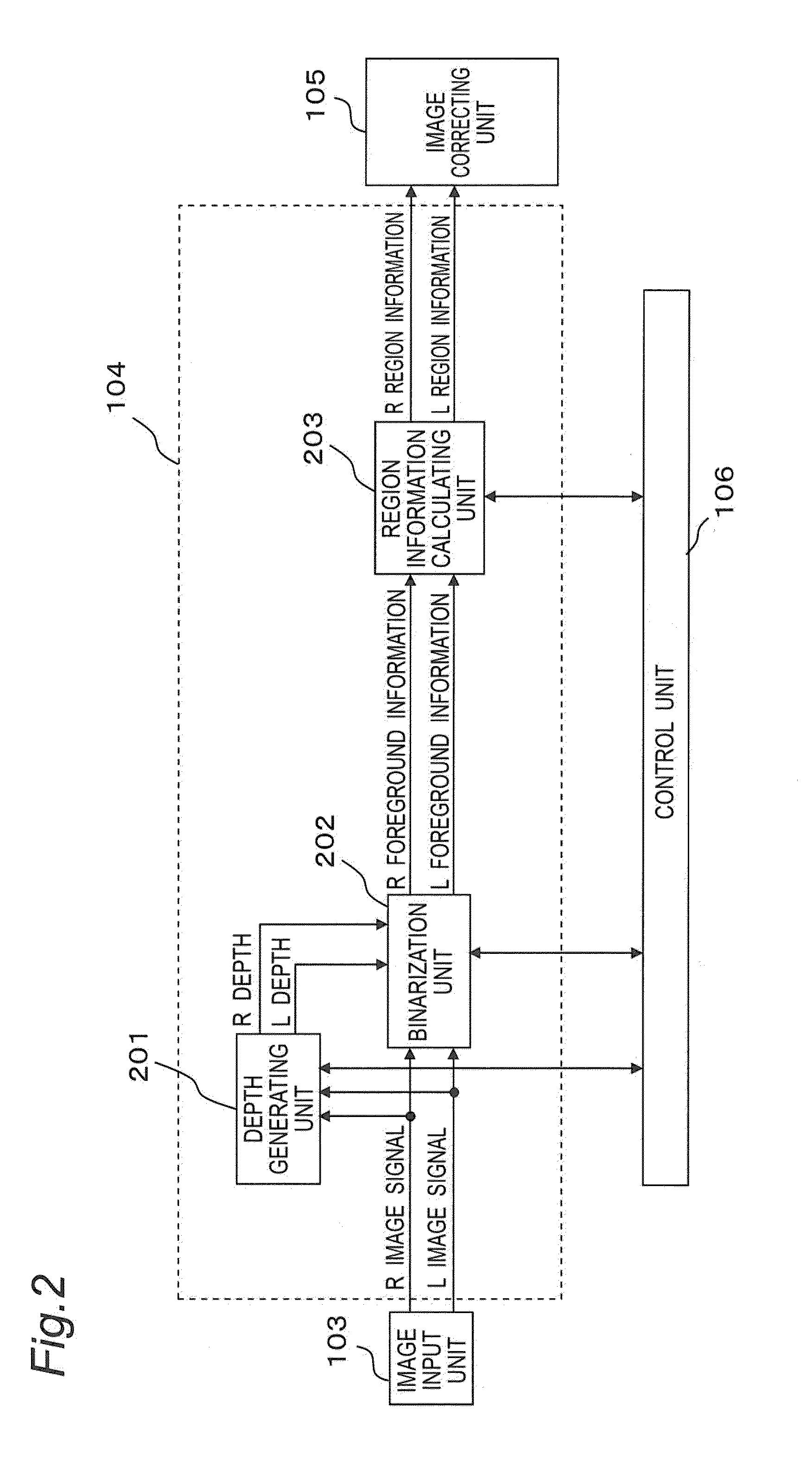
[0047]1.2 Specific Configuration of the Region Extracting Unit

[0048]1.3 Specific Configuration of the Image Correcting Unit

[0049]1.4 Generation Process of the Depth Information

[0050]1.5 Binarization Process

[0051]1.6 Calculation Process of Breadth Information

[0052]1.7 Generation Process of the Parallax Signal

[0053]1.8 Coordinate Transformation Process

[0054]1.8.1 Extension Mode

[0055]1.8.2 Compression Mode

[0056]2. Second Embodiment

[0057]3. Third Embodiment

[0058]4. Fourth Embodiment

[0059]5. Effects and the Like

[0060]6. Other Embodiments

[0061]100>

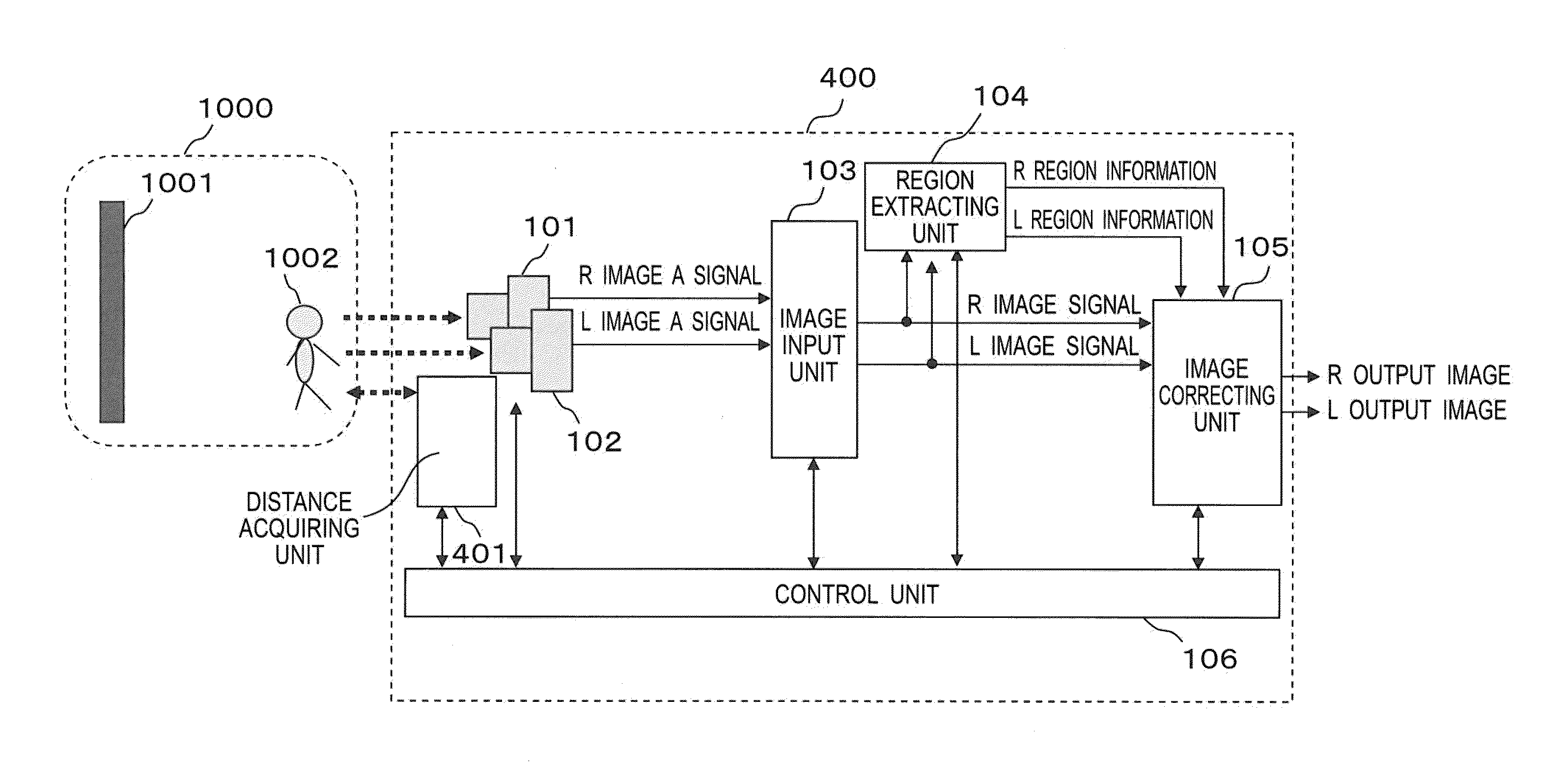
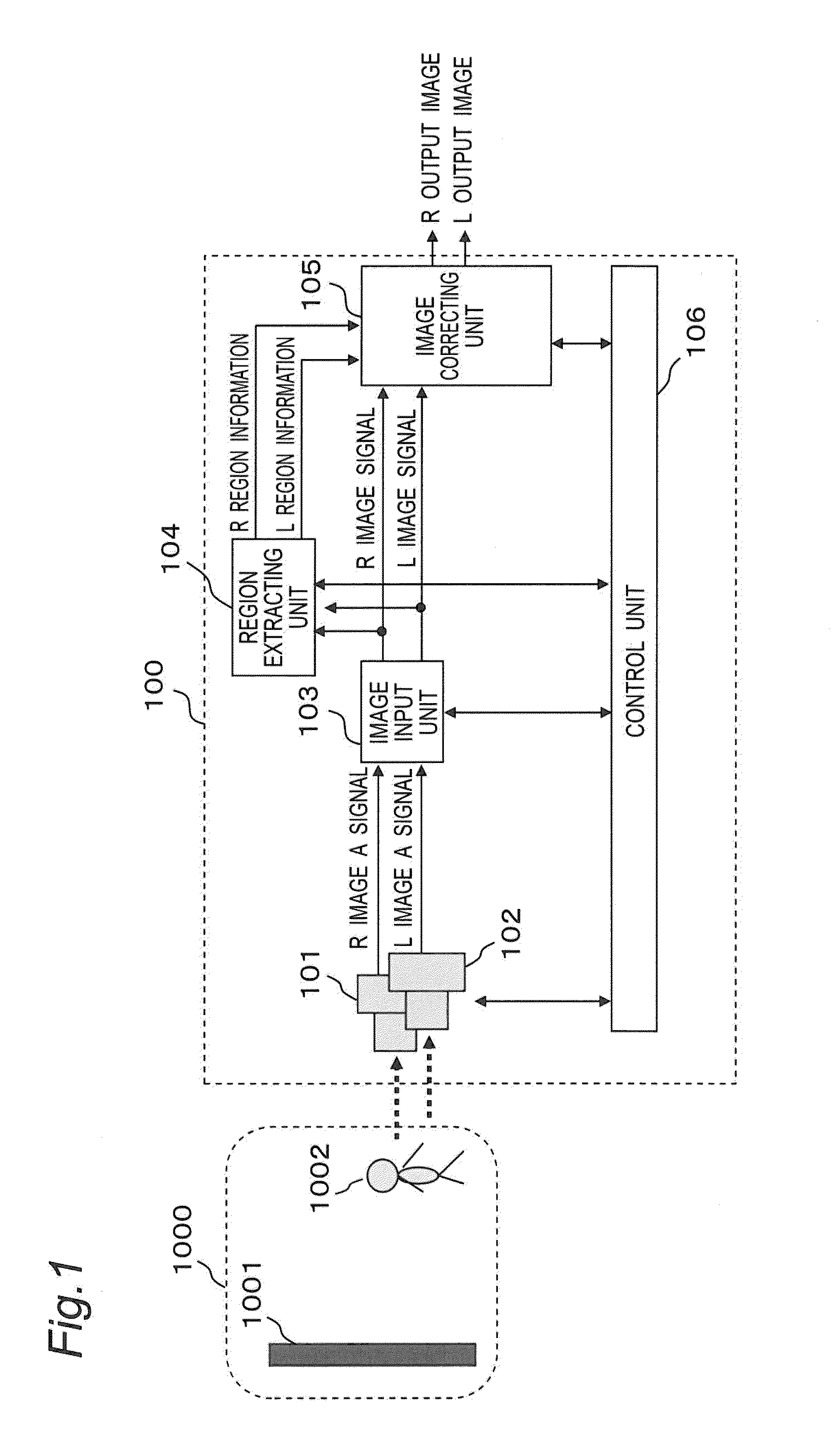
[0062]A configuration of a stereoscopic imaging apparatus (stereoscopic image processing apparatus) according to the present embodiment will be described below with reference to the drawings.

[0063]FIG. 1 is a block diagram illustrating an outline configuration of a stereoscopic imaging apparatus according to the present embodi...

second embodiment

2. Second Embodiment

[0224]In the above described embodiment, the region information calculating unit 203 may change the calculating operation of the width information according to the acquired L depth information or R depth information.

[0225]For example, in calculating the width information, the region information calculating unit 203 operates not to count a pixel for which the region information calculating unit 203 has acquired the L depth information or R depth information exceeding a predetermined threshold. That is, the region information calculating unit 203 assumes that it needs not to resume the depth (thickness) of a subject farther than a predetermined fixed position, thus, calculates the width information of the subject so as not to perform the correction process for giving the above described roundness to the subject.

[0226]The region information calculating unit 203 performs that kind of process because a distant view generally has a poor stereoscopic effect and therefor...

third embodiment

3. Third Embodiment

[0227]In the above described embodiments, the correction process is performed for increasing the parallax for the wider image.

[0228]However, on the condition that the correction process is performed on stereoscopic view images of a subject which is short in the vertical direction like a subject stretching out his arms sideways illustrated in FIG. 20, the positions of the hands are fixed extremely deep in the background so that the image may be perceived as unnatural. Generally, most objects which are short in the vertical direction and long in the horizontal direction in images may have a little thickness in fact.

[0229]By taking account of that tendency, in the present embodiment, the correction process for increasing the parallax is not performed on a part of the extracted subject region which has a length in the vertical direction as long as or less than a predetermined value, i.e., a part which is short in the vertical direction. Specifically, the region inform...


PUM


Abstract

An apparatus including: an acquiring unit operable to acquire a stereoscopic view image which includes a left eye image and a right eye image, the stereoscopic view image representing a stereoscopic image by means of parallax between the left eye image and the right eye image; an extracting unit operable to extract a subject region from the acquired stereoscopic view image, the subject region giving a stereoscopic image of a specific subject; a calculating unit operable to calculate a length of the extracted subject region in a parallax direction; and an image correcting unit operable to adjust parallax at an edge of the subject region based on the calculated length of the subject region in the parallax direction.

Description

CROSS-REFERENCE TO RELATED APPLICATIONS[0001]This is a continuation application of International Application No. PCT / JP2012 / 007647, with an international filing date of Nov. 28, 2012, which claims priority of Japanese Patent Application No. 2011-261406 filed on Nov. 30, 2011, the content of which is incorporated herein by reference.BACKGROUND[0002]1. Technical Field[0003]The present disclosure relates to a stereoscopic image processing apparatus, a stereoscopic image processing method, and a stereoscopic image processing program which improve a visual quality of stereoscopic view images.[0004]2. Related Art[0005]A stereoscopic imaging apparatus configured to capture stereoscopic view images which are to be displayed on a display device (hereinafter, referred to as “stereoscopic display device”) which projects stereoscopic view images including a left eye image and a right eye image on a left eye and a right eye of a viewer independently of each other has been known. The stereoscopic...

Claims


Application Information

Patent Timeline
IPC IPC(8): H04N13/00
CPCH04N13/0007H04N13/128H04N13/239H04N13/106
Inventor ONO, HIROMICHIYAMASHITA, HARUOKUWAHARA, YASUHIROITO, TAKESHI
Owner PANASONIC INTELLECTUAL PROPERTY MANAGEMENT CO LTD
Why Eureka
Try Eureka