Imaging device and imaging method

a technology of imaging device and image, applied in the field of imaging device and imaging method, can solve the problems of limited creative image formation, inability to blur foreground and background, etc., and achieve the effect of reducing parallax

Inactive Publication Date: 2014-09-02
FUJIFILM CORP
View PDF30 Cites 4 Cited by
  • Summary
  • Abstract
  • Description
  • Claims
  • Application Information

AI Technical Summary

Benefits of technology

[0029]The diaphragm control unit is capable of executing second diaphragm control that controls an open amount of the diaphragm unit so as to decrease parallax between corresponding points of the pair of viewpoint images outputted from the imaging unit at the second point of time.

Problems solved by technology

However, if photographing is carried out with a narrowed diaphragm aperture, it is not possible to blur the foreground and the background in contrast to the main subject.
In the pupil dividing-type stereoscopic imaging device, since photographing is carried out with a narrowed diaphragm aperture in order to obtain a clear plane image, creative image formation is limited.

Method used


Image

  • Imaging device and imaging method
  • Imaging device and imaging method
  • Imaging device and imaging method

Examples


first embodiment

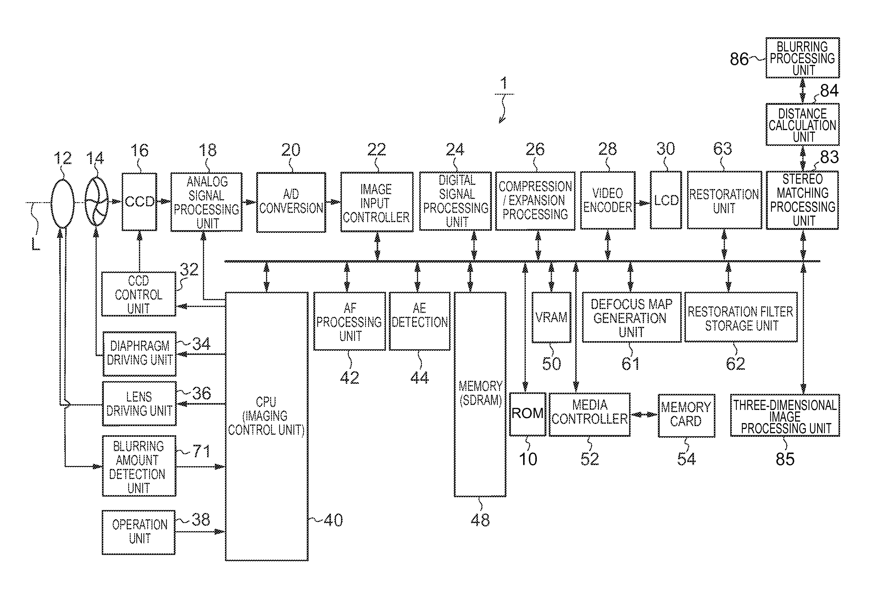
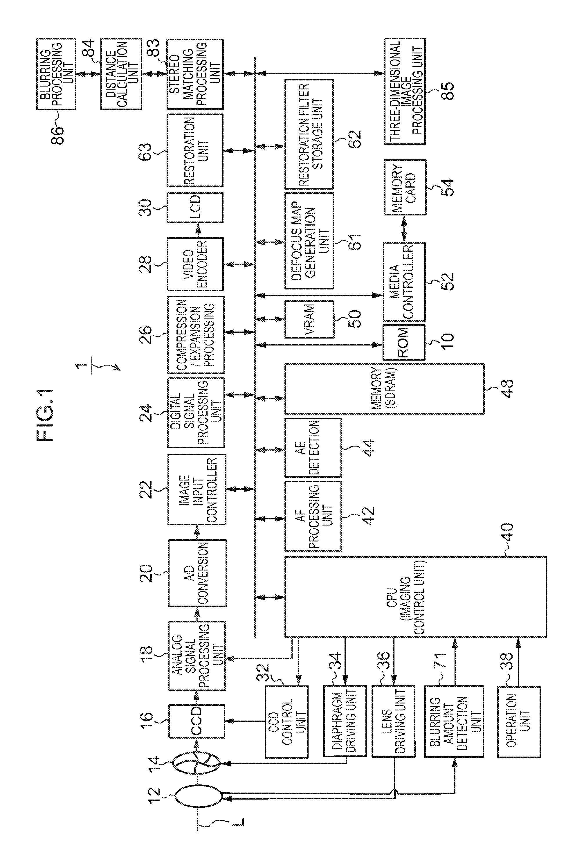
[0042]FIG. 1 is a block diagram showing a mode for implementing a camera 1 according to the first embodiment.

[0043]The camera 1 is configured to record imaged images on a memory card 54, and the operation of the entire device is collectively controlled by a central processing unit (CPU) 40.

[0044]The camera 1 includes an operation unit 38 such as a shutter button, a mode dial, a reproduction button, a MENU / OK key, a cross key, and a BACK key. A signal from the operation unit 38 is inputted into the CPU 40, and the CPU 40 controls each circuit of the camera 1 based on inputted signals. For example, the operation unit 38 performs such control as lens drive control, diaphragm drive control, photographing operation control, image processing control, image data recording / reproduction control, and display control of an LCD monitor (LCD) 30 for stereoscopic display.

[0045]A ROM 10 stores programs executed by the CPU 40 and various data necessary for executing control, pixel defect informatio...

example 1

[0102]The blurring processing unit 86 refers to distance information of each pixel to determine, as the blurring processing target pixels, distant view pixels with a distance larger than a first specified distance (for example, pixels of a subject image with a distance of 5 m or more) or close view pixels with a distance smaller than a second specified distance (for example, pixels of a subject image with a distance of 50 cm or less).

example 2

[0103]The blurring processing unit 86 refers to a parallax map of each pixel to determine, as the blurring processing target pixels, pixels constituting the corresponding points at which a parallax amount between the corresponding points is equal to or larger than a specified value (for example, a value equal to two pixels).


PUM


Abstract

An imaging device, comprising: a single imaging optical system; an imaging unit; a diaphragm unit; a diaphragm control unit; an imaging control unit; a parallax information calculation unit configured to calculate parallax information based on the pair of viewpoint images outputted from the imaging unit at the first point or points of time; a plane image generation unit configured to generate a plane image based on the pair of viewpoint images outputted from the imaging unit at the second point of time; and a blurring processing unit configured to determine target pixels in the plane image which are to be subjected to blurring processing, based on the parallax information calculated by the parallax information calculation unit, and to perform blurring processing on the determined target pixels in the plane image.

Description

CROSS-REFERENCE TO RELATED APPLICATIONS[0001]This application is a continuation application and claims the priority benefit under 35 U.S.C. §120 of PCT Application No. PCT / P2011 / 078649 filed on Dec. 12, 2011 which application designates the U.S., and also claims the priority benefit under 35 U.S.C. §119 of Japanese Patent Application No. 2011-026429 filed on Feb. 9, 2011, which applications are all hereby incorporated by reference in their entireties.BACKGROUND OF THE INVENTION[0002]1. Field of the Invention[0003]The present invention relates to an imaging device and an imaging method for forming subject images on an image sensor, which have respectively passed through different areas of a photographic lens in two directions, to acquire different viewpoint images. The present invention is more particularly relates to an imaging device and an imaging method for stereoscopically displaying a photographing angle of view of an image having parallax as a through image.[0004]2. Descriptio...

Claims


Application Information

Patent Timeline
Patent Type & Authority Patents(United States)
IPC IPC(8): H04N13/02G03B35/08H04N13/122
CPCH04N13/0207H04N13/0296H04N13/0018H04N13/0217G03B35/08H04N13/0257H04N13/122H04N13/218H04N13/257H04N13/296H04N13/207
Inventor ENDO, HIROSHI
Owner FUJIFILM CORP
Why Eureka
Try Eureka