Purge and cooling air for an exhaust section of a gas turbine assembly

a gas turbine and exhaust section technology, applied in the direction of machines/engines, liquid fuel engines, stators, etc., can solve the problem of reducing the overall efficiency of the engin

Active Publication Date: 2014-07-24
SIEMENS ENERGY INC
View PDF10 Cites 71 Cited by
  • Summary
  • Abstract
  • Description
  • Claims
  • Application Information

AI Technical Summary

Benefits of technology

[0009]The turbine assembly may further include an exit orifice at a radially inner end of the strut shield for providing a controlled flow of the purge air from the second purge air path into an inner location of the exhaust casing cavity radially inward from the inner flow path wall. The exit orifice may extend axially downstream from the open cavity within the strut adjacent to the inner casing.

Problems solved by technology

Typically, the cooling systems draw cooling air from the compressor, i.e., bleed air, which can decrease the overall efficiency of the engine.

Method used


Image

  • Purge and cooling air for an exhaust section of a gas turbine assembly
  • Purge and cooling air for an exhaust section of a gas turbine assembly
  • Purge and cooling air for an exhaust section of a gas turbine assembly

Examples


Embodiment Construction

[0029]In the following detailed description of the preferred embodiment, reference is made to the accompanying drawings that form a part hereof, and in which is shown by way of illustration, and not by way of limitation, a specific preferred embodiment in which the invention may be practiced. It is to be understood that other embodiments may be utilized and that changes may be made without departing from the spirit and scope of the present invention.

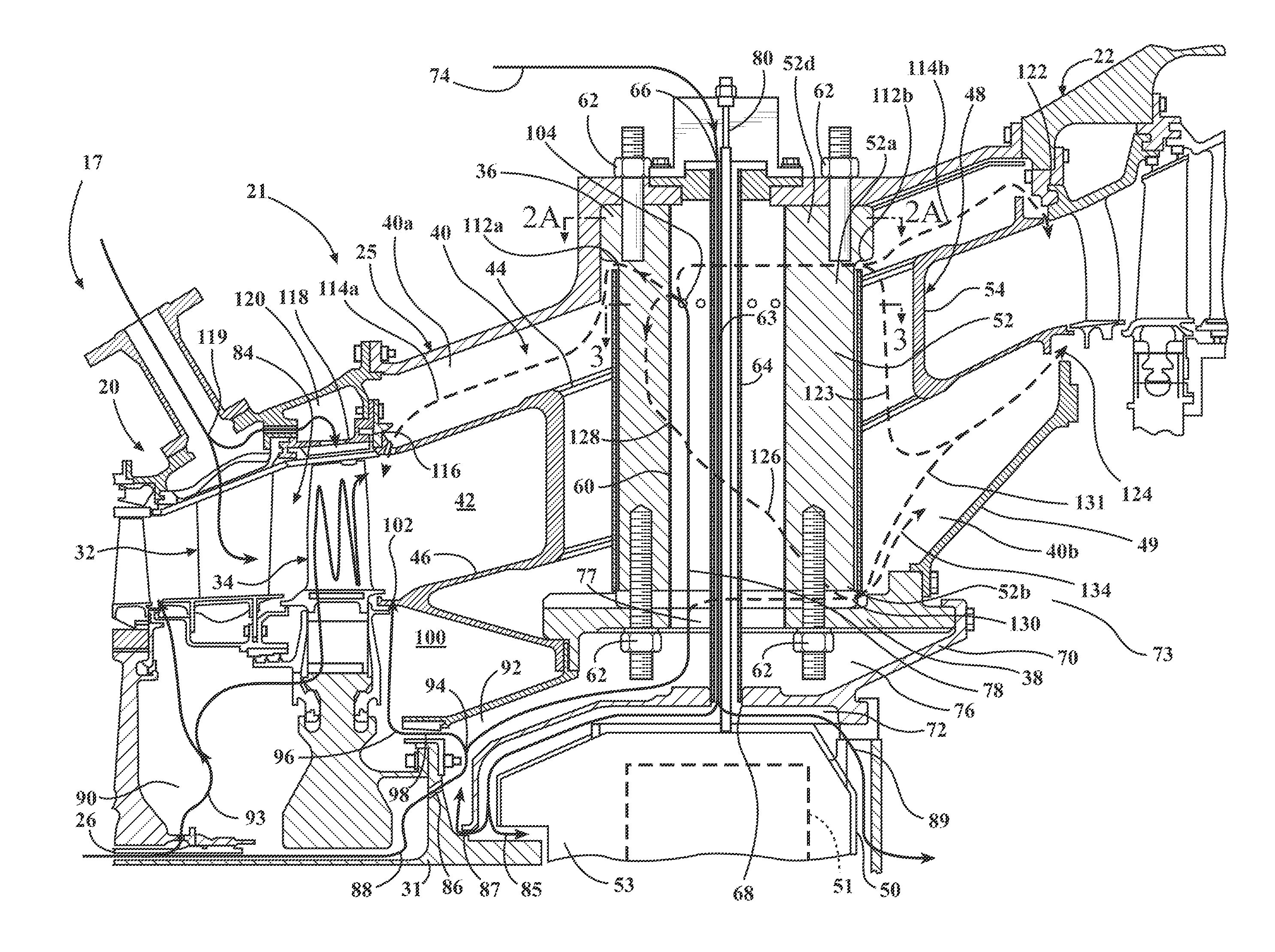
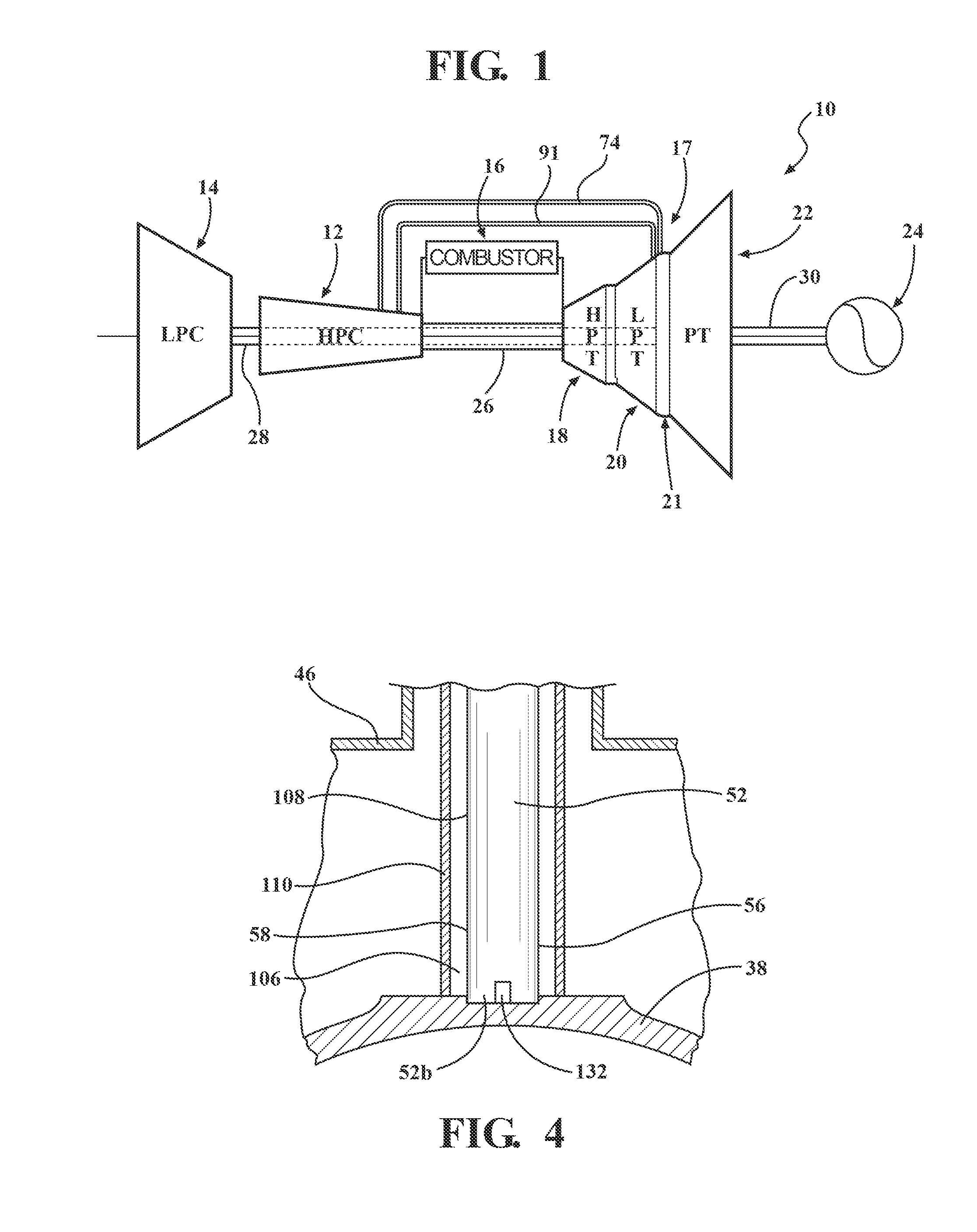
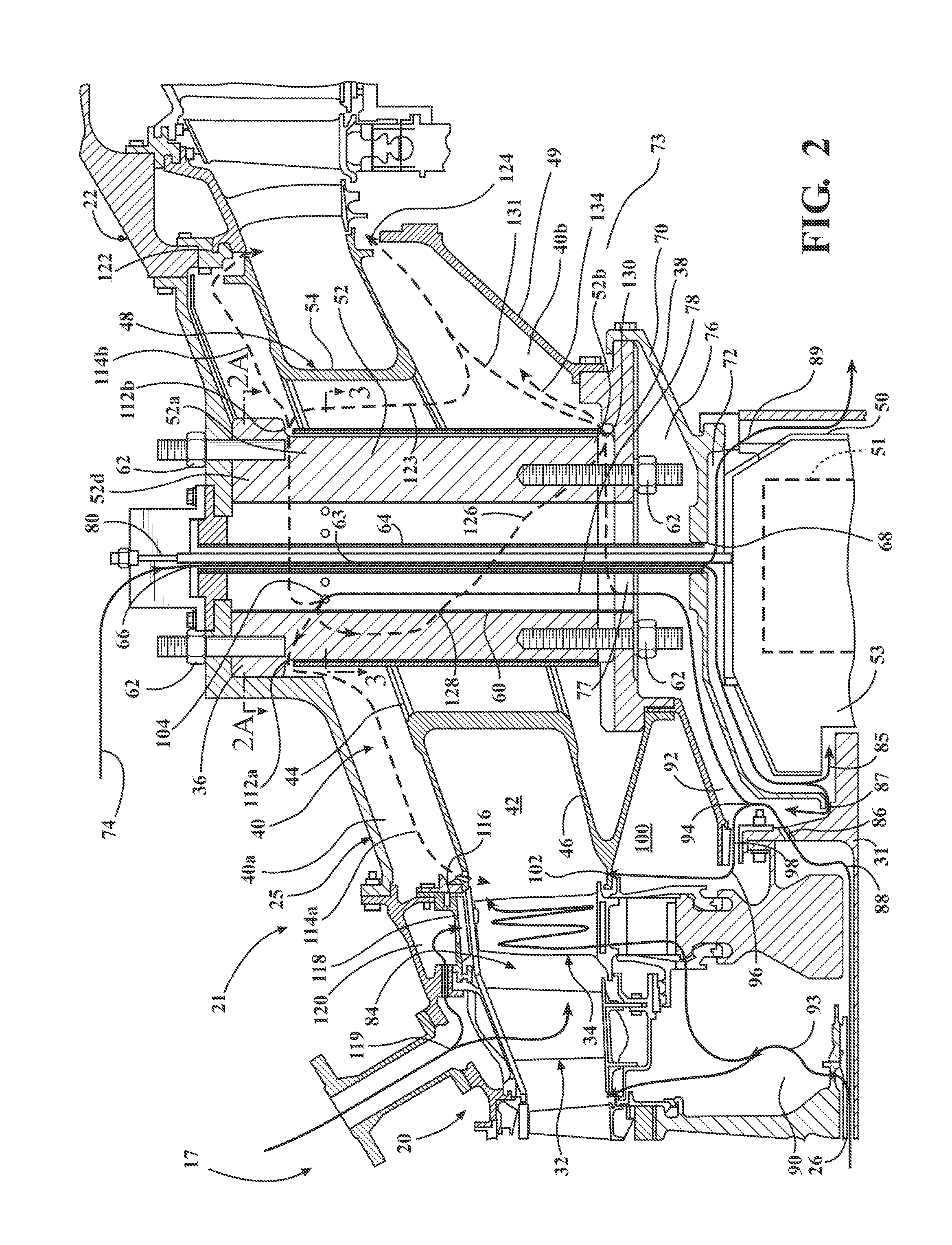
[0030]FIG. 1 schematically illustrates a gas turbine engine 10 that may incorporate the present invention. It should be noted that the particular engine depicted in FIG. 1 comprises an aeroderivative industrial gas turbine engine; however, this invention is not limited to the particular engine described herein. The gas turbine engine 10 comprises a high pressure compressor 12, a low pressure compressor 14, a combustor 16, a turbine section 17 including a high pressure turbine 18, a low pressure turbine 20, and a power turbine 22, and an ...


PUM


Abstract

A turbine exhaust casing having an outer casing, an inner casing, an annular exhaust gas path defined between outer and inner flow path walls, and a turbine exhaust casing cavity located radially outward and radially inward from the gas path. A plurality of structural struts support the inner casing to the outer casing, and a fairing surrounds each of the struts in an area extending between the outer and inner flow path walls. A first purge air path extends through at least one of the struts for conducting purge cooling air radially inward to the inner casing, and a second purge air path extends through the strut for further conducting the purge cooling air radially outward to provide a flow of purge air to a location of the exhaust casing cavity radially outward from the outer flow path wall.

Description

FIELD OF THE INVENTION[0001]The present invention relates to a gas turbine engine and, more particularly, to cooling of components located at a gas turbine exhaust assembly of a turbine section for the engine.BACKGROUND OF THE INVENTION[0002]In a turbomachine, such as a gas turbine engine, air is pressurized in a compressor then mixed with fuel and burned in a combustor to generate hot combustion gases. The hot combustion gases are expanded within a turbine section including a turbine assembly where energy is extracted to power the compressor and to produce useful work, such as powering a generator to produce electricity. The hot combustion gas travels through a series of turbine stages. A turbine stage may include a row of stationary vanes followed by a row of rotating turbine blades, where the turbine blades extract energy from the hot combustion gas for powering the compressor and may provide output power. The combustion gases are exhausted through a gas path located within a tur...

Claims


Application Information

Patent Timeline
Patent Type & Authority Applications(United States)
IPC IPC(8): F02C7/18F01D25/16F02C6/08
CPCF01D9/065F01D25/12F01D25/125F02C6/08F05D2240/15F02C7/18F01D25/162F01D25/30F01D9/02
Inventor PATAT, HARRYSCHOPF, CHERYL A.KATY, JEROME H.WALLACE, ADAMWIEBE, DAVID J.
Owner SIEMENS ENERGY INC
Why Eureka
Try Eureka