Knee rehabilitation device with measurement element

a technology of measurement element and knee joint, which is applied in the field of mechanical devices, can solve the problems of extension contracture, loss of ability to flex the body joint,

Active Publication Date: 2014-07-24
PROMOTUS
View PDF3 Cites 13 Cited by
  • Summary
  • Abstract
  • Description
  • Claims
  • Application Information

AI Technical Summary

Benefits of technology

[0017]A first embodiment knee rehabilitation device is machined or cast from a lightweight structural metal, such as titanium, aluminum or magnesium. The device includes a generally U-Shaped handle of adjustable length that is rotatably coupled to a parallel-beam leg support. The leg support provides attachment points for an upper band that bridges the gap between the parallel beams and two pair of longitudinal slots, in which can slide a middle band and a lower band. The middle and lower bands also bridge the gap between the parallel beams. The lower band, which is used to support the leg beneath the ankle, slides within the lower of the two pair of longitudinal slots so that different leg sizes can be accommodated. The middle band, which fits over the anterior portion of the leg and inferior to the knee, can also be slid within the upper of the two pair of longitudinal slots. The adjustability of the middle band allows for different forces to be applied to the knee joint when a force is applied by the user of the device. The upper band, the position of which is non-adjustable, fits over the anterior portion of the leg either above or below the knee.

Problems solved by technology

Weakness, disuse, fractures, surgeries, illness, and other causes have been known to cause loss of ability to flex the body joint otherwise known as an extension contracture.

Method used


Image

  • Knee rehabilitation device with measurement element
  • Knee rehabilitation device with measurement element
  • Knee rehabilitation device with measurement element

Examples


first embodiment

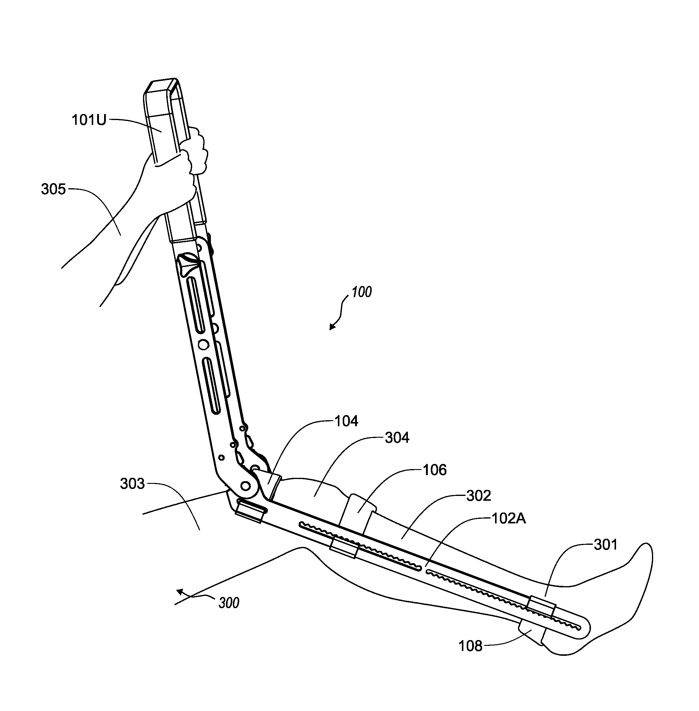
[0052]Referring now to FIG. 3, the first embodiment knee rehabilitation device 100 is shown being used by a patient 300 in its standard operational mode.

[0053]Referring now to FIGS. 4, 5 and 6, the first embodiment knee rehabilitation device 100 is being used by a patient 300 to rotate his knee 304 through various degrees of motion in FIGS. 4 and 5 to full extension in FIG. 6. It will be noted that for this therapy regime, the upper band 104 (also referred to as a band) is 15 positioned on the anterior portion of the thigh 303 just above the knee 304, the middle band 106 passes over the anterior portion of the lower leg 302 just below the knee 304, and the lower band 108 supports the lower leg 302 just posterior to the ankle 301. FIGS. 4, 5 and 6 show the first embodiment knee rehabilitation device in use by a patient 300 in its first, or standard, configuration, with the upper band 104 positioned just above the knee 304 on the anterior of the patient's thigh 303, the middle band 10...

third embodiment

[0063]Referring now to FIGS. 18 and 19, a third embodiment knee rehabilitation device 1800 has a non-adjustable tubular metal frame 1801 in which the handle portion 1801A is rigidly affixed to a leg support portion 1801B. An upper band 1802, a middle band 1803 and a lower band 1804 can be slidably positioned along the parallel tubes of the leg support portion 1801B.

fourth embodiment

[0064]Referring now to FIGS. 20, 21 and 22, a fourth embodiment knee rehabilitation device 2000 has a non-adjustable frame 2001 made of a pair of laminar sheet material components 2001A and 2001 B disposed in a mutually-parallel configuration. The laminar sheet material can be a structural metal such as aluminum, steel alloys, stainless steel alloys, magnesium alloys and titanium. It can also be a polymeric material, such as polyester thermoplastic resin that is reinforced by structural fibers such as para-aramid (e.g., Kevlar®), glass and carbon. Each of the frame components 2001A and 2001B is reminiscent of a hockey stick or boomerang, with a first end 2002A and 2002B of each serving as a handle and the other end 2003A and 2003B serving as half of the leg support portion. Front, middle and rear bands (2004, 2005 and 2006, respectively) bridge the gap between the two frame components 2001A and 2001B. Each frame component is equipped with a pair of longitudinal slots 2007A, 2008A an...


PUM


Abstract

In one example, a rehabilitation device includes a first element having first and second spaced-apart, generally parallel elongate members having proximal and distal ends. A second element is rotatably coupled to the first element and includes first and second spaced-apart, generally parallel elongate members having proximal and distal ends. One of the first and second elements is angularly adjustable relative to the other. A measurement device includes a measurement element connected to one of the first and second elements and configured for rotation relative to one of the first and second elements, such that when the rehabilitation device is operably disposed with respect to a joint of a patient, the measurement element is arranged for contact with anatomy of the patient. Finally, a scale is disposed proximate the measurement element and indicates a position of the measurement element relative to another portion of the rehabilitation device.

Description

RELATED APPLICATIONS[0001]This application is a continuation-in-part (CIP) of, and hereby claims priority to, U.S. patent application Ser. No. 13 / 048,861, entitled KNEE REHABILITATION DEVICE, and filed on Mar. 15, 2011 (the “'861 Application”). The '861 Application, in turn, claims priority to U.S. Provisional Patent Application No. 61 / 314,135, entitled KNEE REHABILITATION DEVICE, and filed on Mar. 15, 2010. All of the aforementioned applications are incorporated herein in their entireties by this reference.BACKGROUND OF THE INVENTION[0002]This invention relates generally to mechanical devices used to facilitate knee range of motion, which can be used in various stages of knee rehabilitation and more particularly, to an apparatus that can be used by a patient, with or without the aid of medical personnel, to engage in full joint flexibility following a knee impairment which can be used in multiple positions, by multiple methods, and multiple locations due to convenience of size and ...

Claims


Application Information

Patent Timeline
Patent Type & Authority Applications(United States)
IPC IPC(8): A61H1/02
CPCA61H2201/1269A61H1/024A61H2201/0161A61H2201/1642
Inventor HALL, JACOB RANDY
Owner PROMOTUS
Why Eureka
Try Eureka