Anchoring of prosthetic valve supports

Active Publication Date: 2014-07-24
CARDIOVALVE LTD
View PDF1 Cites 327 Cited by
  • Summary
  • Abstract
  • Description
  • Claims
  • Application Information

AI Technical Summary

Benefits of technology

[0013]For some applications of the invention, a prosthetic valve support is provided for facilitating minimally invasive (e.g., transcatheter and/or transluminal) implantation of a prosthetic valve at a native valve of a subject. The native valve typically has native check valve functionality, i.e., it functions as a check valve. The prosthetic valve support is typically couplable to the native valve (e.g., to leaflets thereof) of the subject without eliminating the check valve functionality of the native valve. The prosthetic valve is subsequently implanted a

Problems solved by technology

Regurgitation of blood from the ventricle into the atrium results in increased total stroke volume and decreased cardia

Method used


Image

  • Anchoring of prosthetic valve supports
  • Anchoring of prosthetic valve supports
  • Anchoring of prosthetic valve supports

Examples


Embodiment Construction

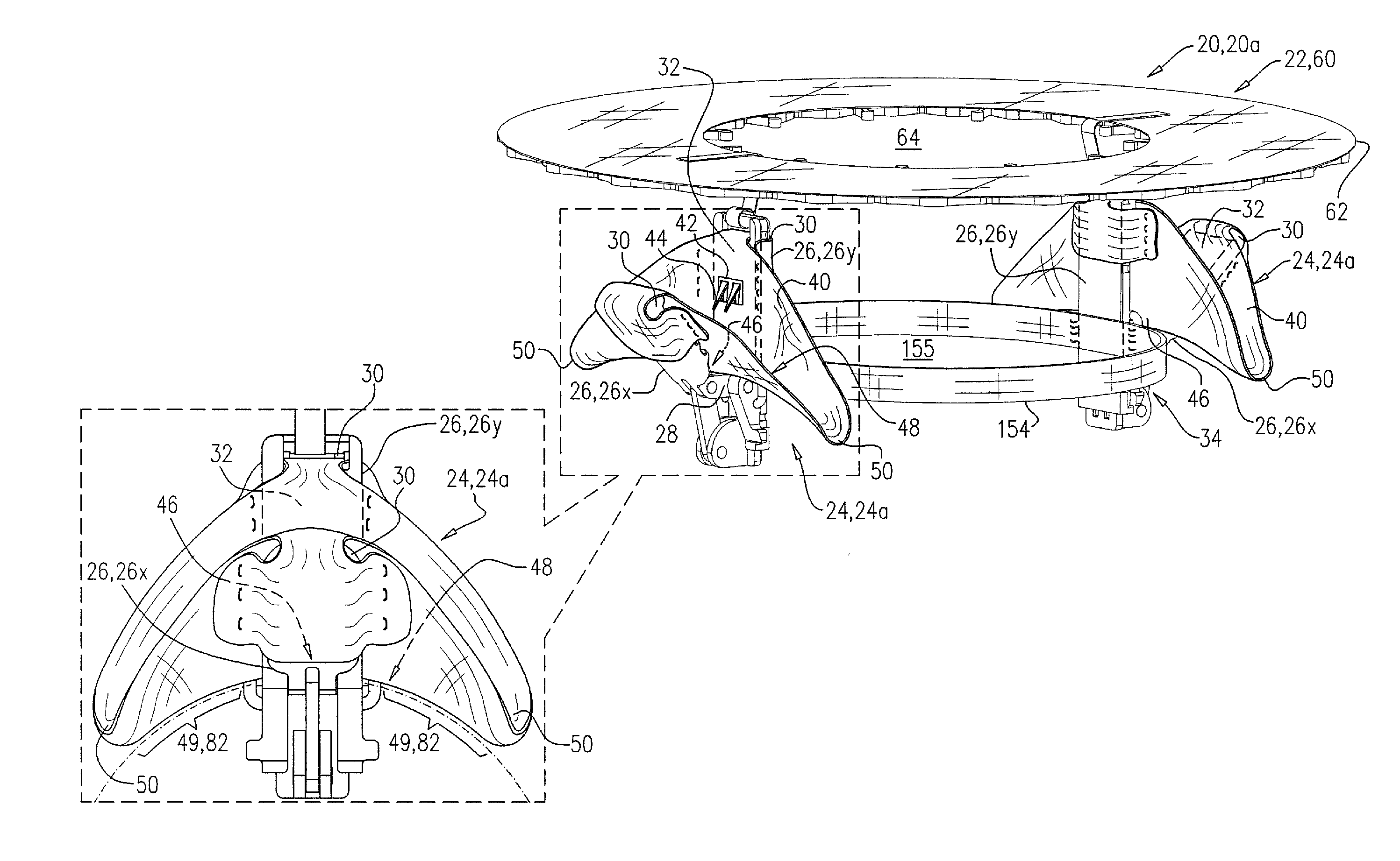
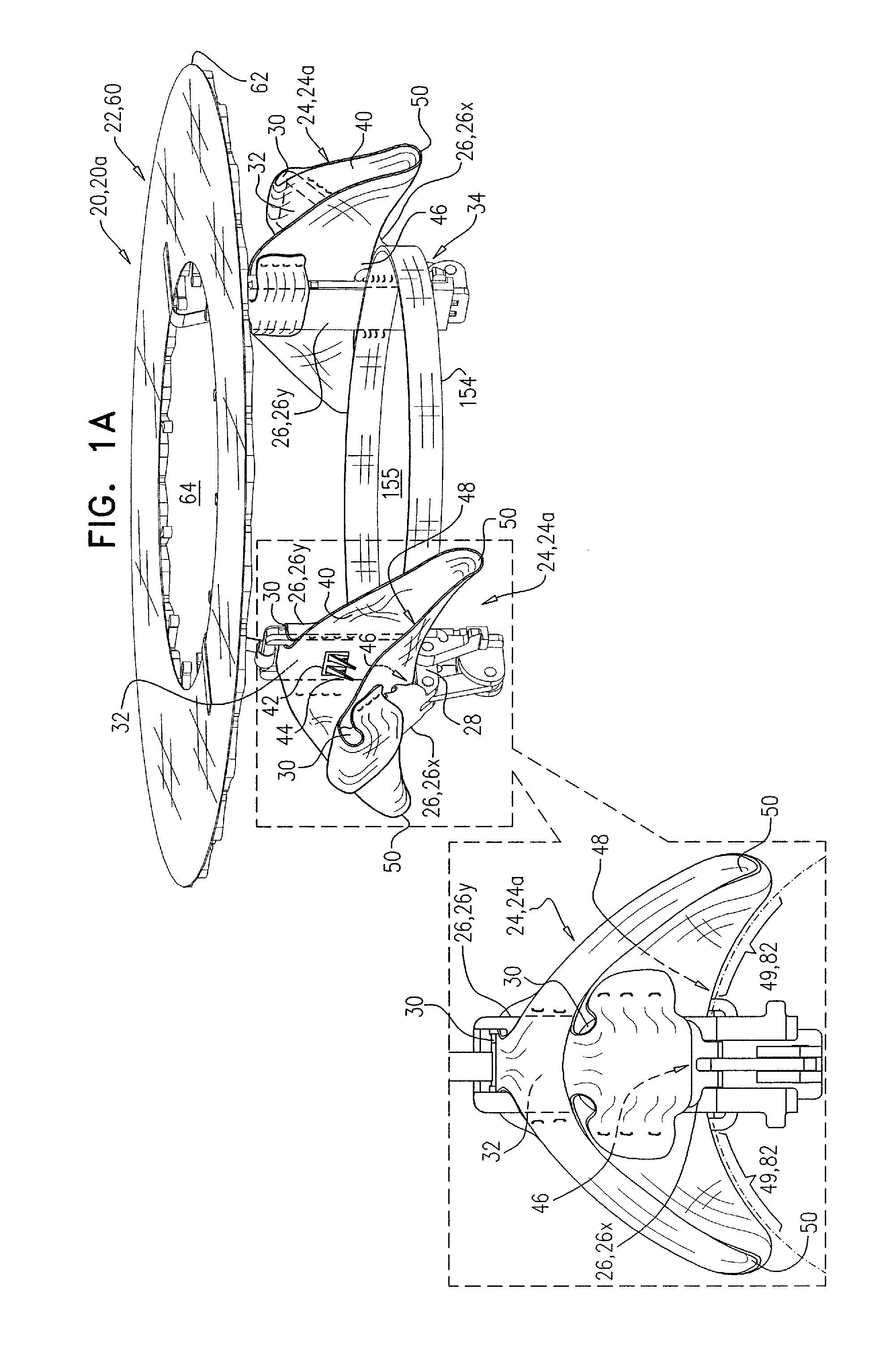
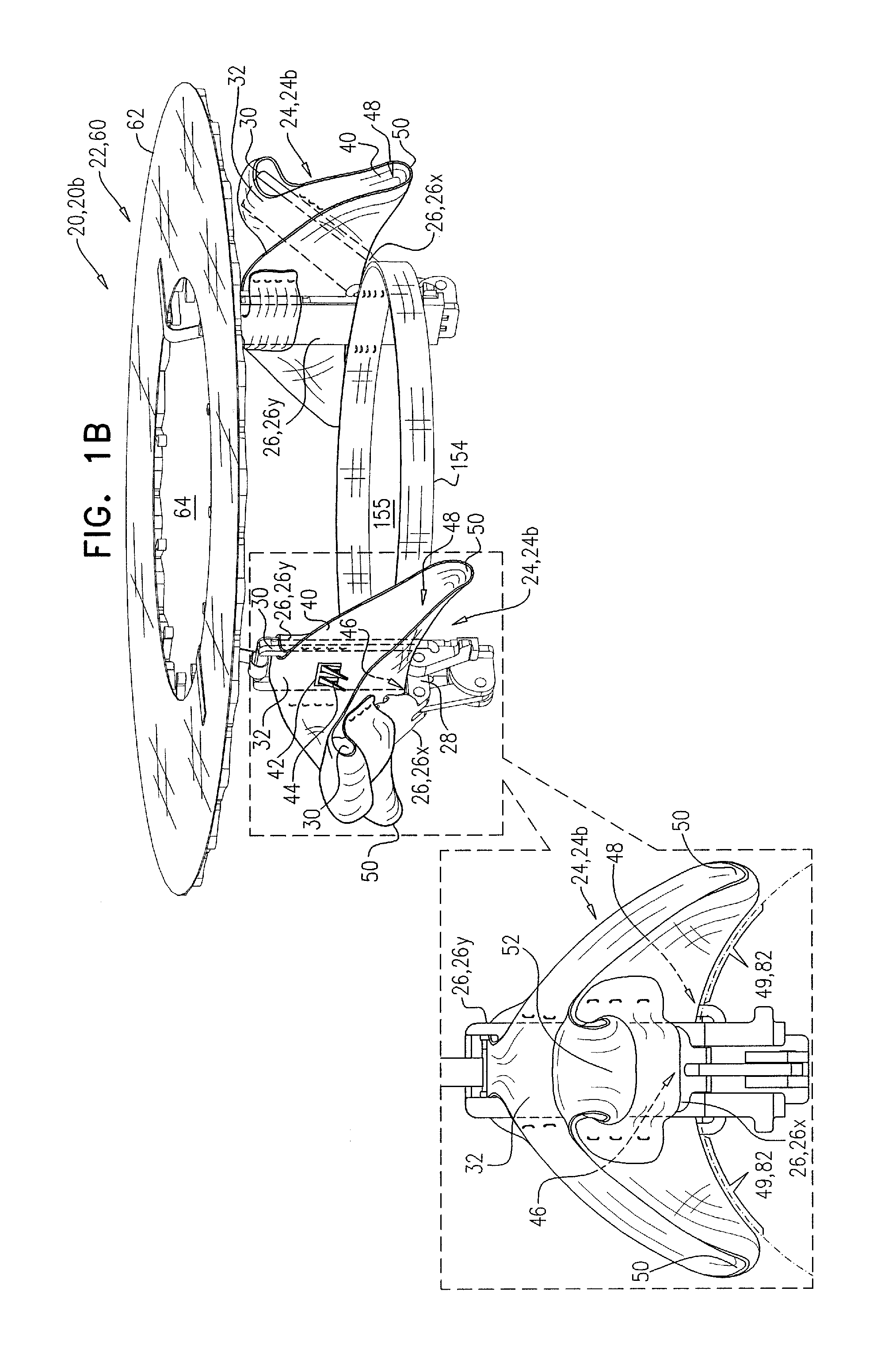
[0166]Reference is made to FIGS. 1A-C and 2, which are schematic illustrations of a system 20 comprising an implant 22, and apparatus for facilitating implantation of the implant at a native heart valve 10 of a subject, the apparatus comprising a tissue-engaging element 24, in accordance with some applications of the invention. FIG. 1A shows system 20 comprising a system 20a, and tissue-engaging element 24 comprising a tissue-engaging element 24a, in accordance with some applications of the invention. FIG. 1B shows system 20 comprising a system 20b, and tissue-engaging element 24 comprising a tissue-engaging element 24b, in accordance with some applications of the invention. FIG. 1C shows system 20 comprising a system 20c, and tissue-engaging element 24 comprising a tissue-engaging element 24c, in accordance with some applications of the invention. FIG. 2 shows system 20b having been implanted at native valve 10, in accordance with some applications of the invention.

[0167]Tissue-eng...


PUM


Abstract

Apparatus is provided, including: (1) a delivery tube, transluminally advanceable to the heart of the subject; (2) a prosthetic valve support, configured to support a prosthetic valve at a native valve of the heart, and including an upstream support portion, the upstream support portion: (A) having a working configuration in which it is generally annular and (B) having a delivery configuration in which it defines a channel, and is configured to be disposed within the delivery tube; (3) a tissue anchor, slidable through the channel; and (4) an anchor driver. The anchor driver is slidable within the delivery tube and the channel, and configured to anchor the upstream support portion to tissue of the heart by driving the tissue anchor through the upstream support portion and into the tissue, while at least part of the upstream support portion is disposed within the delivery tube.

Description

CROSS-REFERENCES TO RELATED APPLICATIONS[0001]The present application claims priority from U.S. Provisional Patent Application 61 / 756,034 to Hacohen et al., filed Jan. 24, 2013, and entitled “Tissue-engaging elements”; and U.S. Provisional Patent Application 61 / 756,049 to Hacohen et al., filed Jan. 24, 2013, and entitled “Ventricularly-anchored prosthetic valve support”,[0002]and is related to:[0003]US patent application publication 2012 / 0022639 to Hacohen et al., filed Jul. 21, 2010;[0004]US patent application publication 2012 / 0022640 to Gross et al., filed Feb. 24, 2011;[0005]U.S. patent application Ser. No. 13 / 811,308 to Gross et al., filed Jan. 21, 2013, which published as US 2013 / 0172992;[0006]U.S. patent application Ser. No. 13 / 412,814 to Gross et al., filed Mar. 6, 2012, which published as US 2013 / 0035759;[0007]PCT patent application IL2012 / 000292 to Gross et al., filed Aug. 5, 2012, which published as WO / 2013 / 021374;[0008]PCT patent application IL2012 / 000293 to Gross et al.,...

Claims


Application Information

Patent Timeline
IPC IPC(8): A61F2/24
CPCA61F2/2427A61F2/2418A61F2220/0025A61F2220/0016A61F2/2409A61F2220/0075A61F2250/0098A61F2/2436A61F2210/0076
Inventor HACOHEN, GILIMILLER, ERANREICH, TALZIPORY, YUVALNEEMAN, ROTEMKRUGLOVA, NATALIA
Owner CARDIOVALVE LTD
Why Eureka
Try Eureka