Line projection system

a projection system and line technology, applied in the field of marking, can solve the problems of simple wear through in sections, scuffing and torn tape, and easy scuffing of optical tap

Inactive Publication Date: 2014-07-24
QUNOMIC VIRTUAL TECH
View PDF0 Cites 28 Cited by
  • Summary
  • Abstract
  • Description
  • Claims
  • Application Information

AI Technical Summary

Benefits of technology

[0014]The present invention comprises a laser-based line projection system that is suitable for selectively placing lines on a floor surface, such as a factory floor. Several projectors are used in a typical installation. Each projector includes a laser directed through a diverging lens to create a planar projection of laser light. The planar projection creates a bright line when it falls on a surface. Each projector is optionally equipped with a movable mask that alters the angle of divergence for the laser light after it passes through the diverging lens. This component allows the projector to vary the length of the line projected.

Problems solved by technology

The use of optical tape has well known disadvantages.
The tape may become scuffed and torn.
In prolonged use it may simply wear through in sections.
Many use lay multiple tape layers on the same path until the height of the tape becomes a problem.
This is a time consuming and labor intensive process.

Method used


Image

  • Line projection system
  • Line projection system
  • Line projection system

Examples


Embodiment Construction

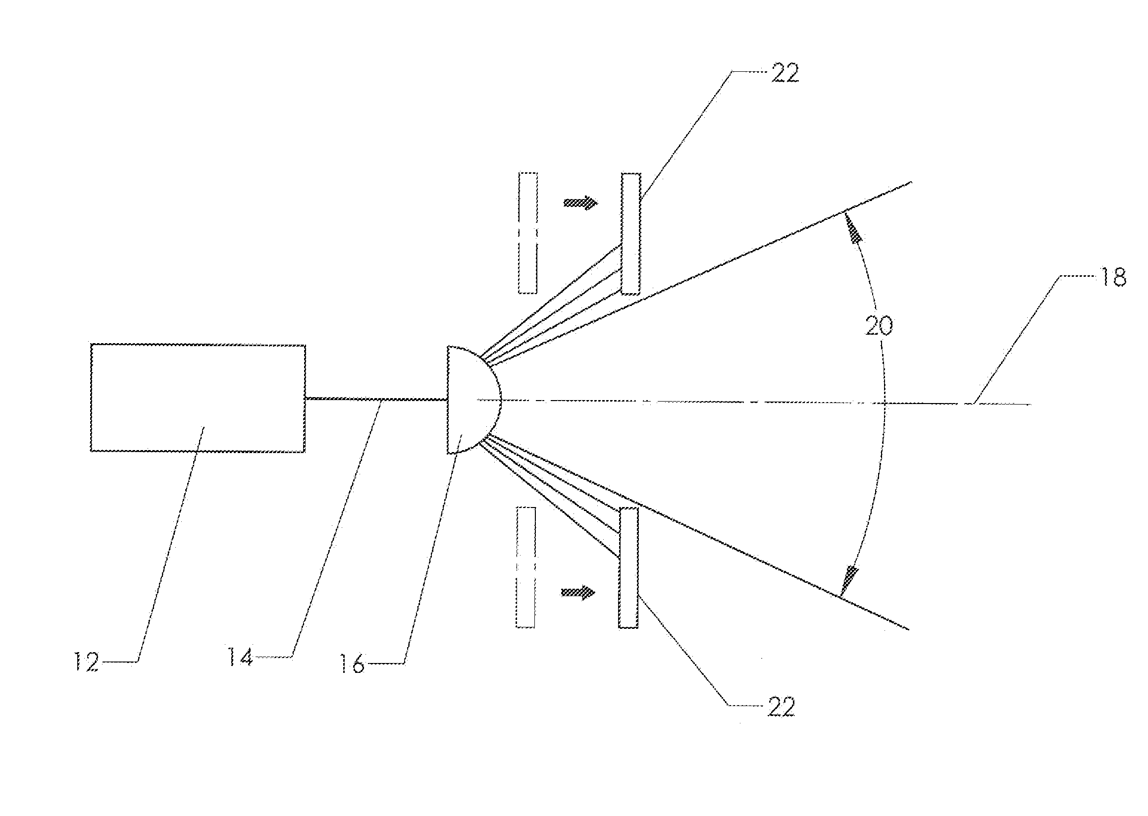
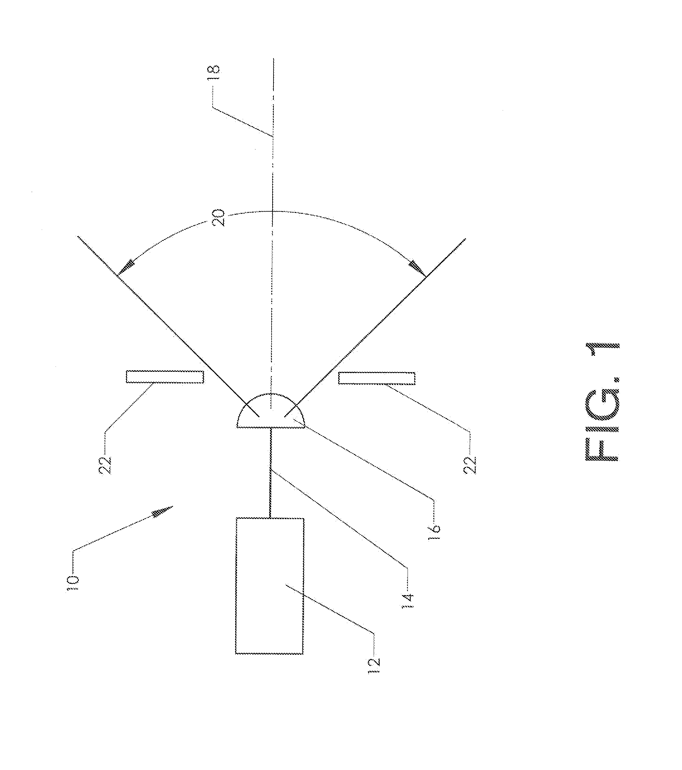
[0027]FIG. 1 shows a simplified depiction of a line projector 10 Laser 12 produces beam 14 of coherent light. A diverging lens is placed in the path of the beam. The term “diverging lens” refers to any component capable of spreading the beam into a plane of light. A common example is a cylindrical lens In the embodiment of FIG. 1, diverging lens 16 is placed in the path of the beam. The diverging lens creates a diverging “fan” of coherent light that diverges at an angle 20 with respect to projection axis 18.

[0028]As is well known to those skilled in the art, when a laser beam strikes a surface it creates a brilliant point of light (produced by the backscatter phenomenon inherent in diffuse reflection). When a diverging fan such as shown in FIG. 1 strikes a surface it creates a line. The line that is thereby projected is used in the present invention.

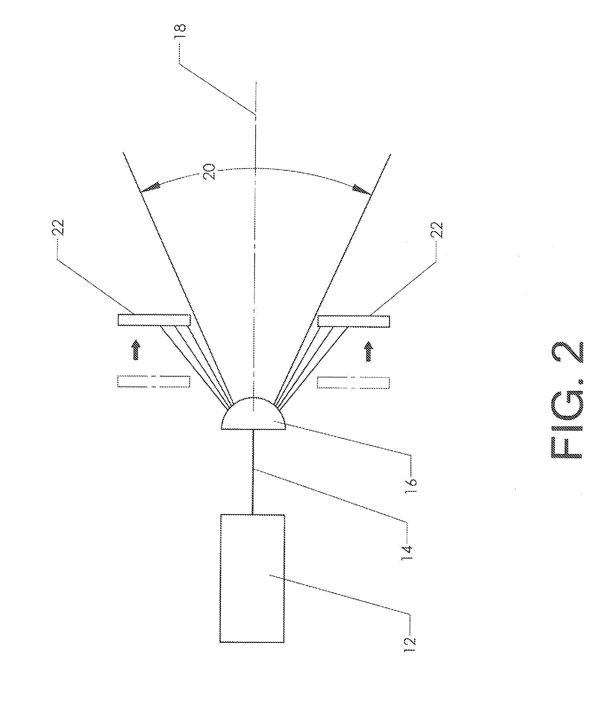
[0029]It is preferable to include a mask 22. A mask is simply an occluding device with an opening to allow all or part of the diverging...


PUM


Abstract

A laser-based line projection system that is suitable for selectively placing lines on a floor surface, such as a factory floor. Several projectors are used in a typical installation. Each projector includes a laser directed through a diverging lens to create a planar projection of laser light. The planar projection creates a bright line when it falls on a surface. Each projector is optionally equipped with a movable mask that alters the angle of divergence for the laser light after it passes through the cylindrical lens. This component allows the projector to vary the length of the line projected.

Description

CROSS-REFERENCES TO RELATED APPLICATIONS[0001]Not ApplicableSTATEMENT REGARDING FEDERALLY SPONSORED RESEARCH OR DEVELOPMENT[0002]Not Applicable.MICROFICHE APPENDIX[0003]Not ApplicableBACKGROUND OF THE INVENTION[0004]1. Field of the Invention[0005]This invention relates to the field of marking. More specifically, the invention comprises a system for projecting an illuminated line on a floor. The line may serve to guide automated vehicles, to segregate one area from another, and for many other purposes.[0006]2. Description of the Related Art[0007]A line placed on a floor surface can serve a wide variety of purposes. A simple use for such a line is separating two areas. An example of this would be identifying a boundary between an area where fork trucks are allowed to operate and another area where they are not In recent years, lines placed on a floor surface have also been used to define a route for an automatically guided vehicle (“AGV”).[0008]AGV's routinely handle transport tasks i...

Claims


Application Information

Patent Timeline
Patent Type & Authority Applications(United States)
IPC IPC(8): G05D1/02
CPCG05D1/0236G05D2201/0216
Inventor MURPHY, TERRY
Owner QUNOMIC VIRTUAL TECH
Why Eureka
Try Eureka