Flue gas-heat recovery cooling and heating system

A technology for cooling, heating, and heating systems, which is used in heating and cooling combinations, refrigerators, refrigeration components, etc., can solve the problems of uneconomical, high operating costs, and high boiler exhaust gas temperature, and achieve good economic and social benefits. , the effect of reducing electricity or fuel consumption, reducing pollution

Inactive Publication Date: 2011-02-02
XINHUI SHUANGSHUI POWER B PLANT CO LTD
View PDF8 Cites 1 Cited by
  • Summary
  • Abstract
  • Description
  • Claims
  • Application Information

AI Technical Summary

Problems solved by technology

[0002] The 150MW, 480t / h circulating fluidized bed ultra-high temperature and ultra-high pressure units currently in operation in the power plant have high efficiency, but the boiler exhaust gas temperature is about 45°C higher than the design temperature, which is about 152°C. Therefore, the recovery of boiler flue gas waste heat There is a lot of space to use, and with the increasing shortage of energy, it is imperative to implement energy saving and consumption reduction work
[0003] On the other hand, the power plant and surrounding users all use electricity for cooling and electricity or gas for hot water. Compared with this energy-saving project, the energy has been converted many times, and the comprehensive utilization efficiency of energy is low. economic issues

Method used


Image

  • Flue gas-heat recovery cooling and heating system
  • Flue gas-heat recovery cooling and heating system

Examples


Embodiment 1

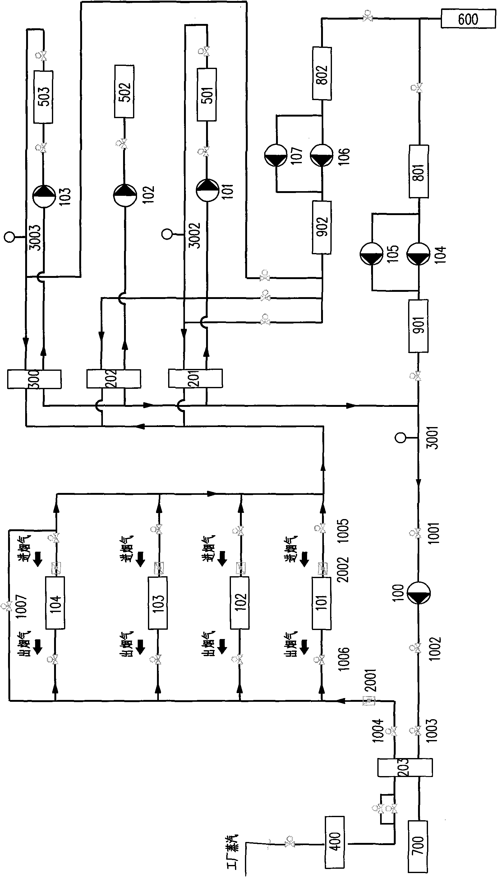
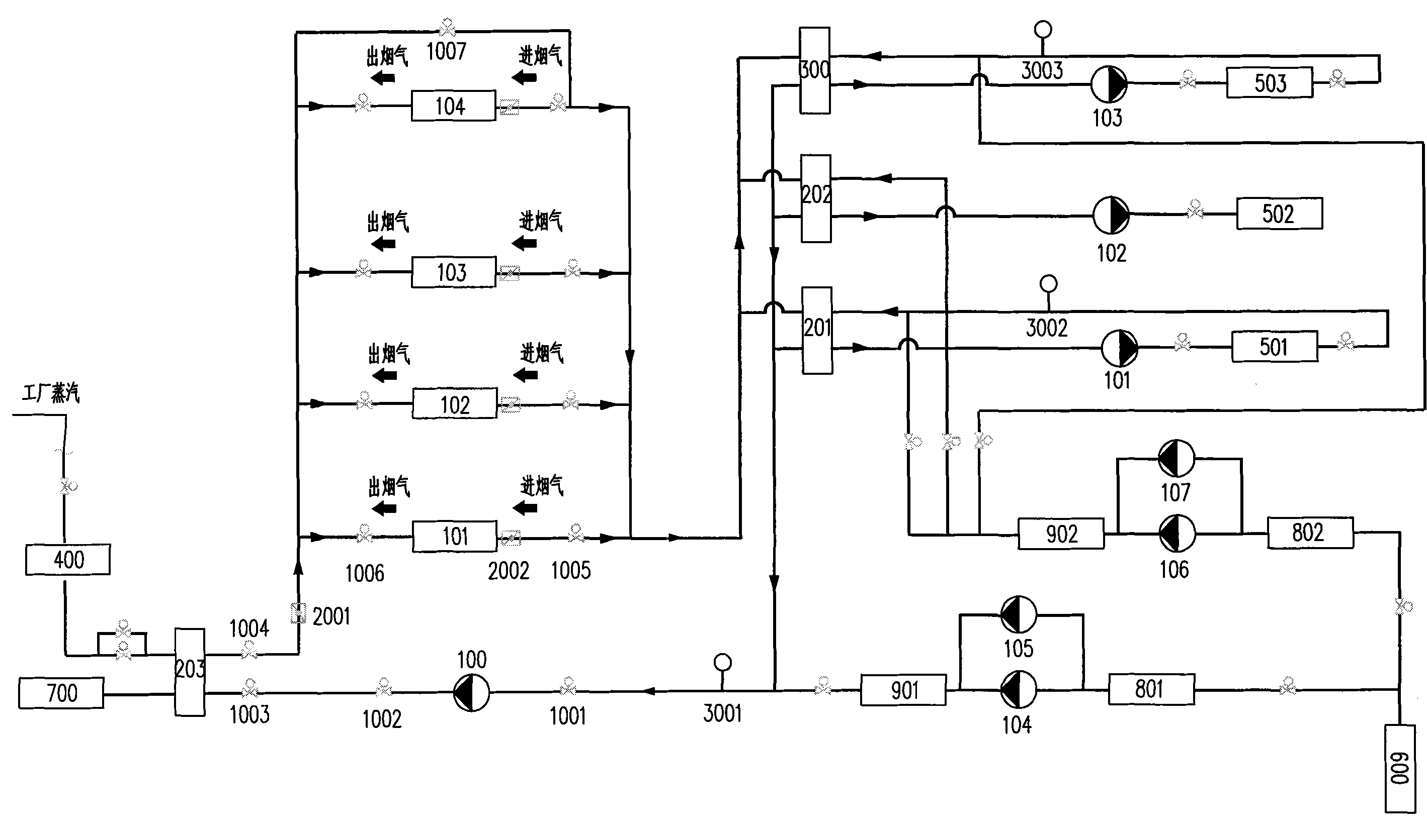
[0045] As shown in Figure 1, the flue gas-heat recovery refrigeration and heating system according to the present invention includes a hot water pump 100, a first flue gas-heat recovery device 101, a first plate heat exchanger 201, a No. 1 pump 101, a No. Second plate heat exchanger 201, No. 2 pump 102, lithium bromide refrigerator 300, No. 3 pump 103, third plate heat exchanger 203, factory steam temperature reduction and decompression device 400, water supply device, domestic hot water user terminal 502, air conditioner The hot water user terminal 501, the air conditioner chilled water user terminal 503 and the system control circuit, the input end of the hot water pump 100 is respectively connected to the first plate heat exchanger 201, the second plate heat exchanger 202 and the first exchange of the lithium bromide refrigerator 300 The output end of the flow channel is connected, the input end of the second exchange flow channel of the third plate heat exchanger 203 is con...

Embodiment 2

[0057] This embodiment is similar to Embodiment 1, except that the system is used to prepare hot water for air-conditioning and domestic hot water, and does not prepare chilled water for air-conditioning, that is, the system does not include the refrigerator 300, the user terminal 503 for chilled water for air-conditioning and the corresponding pipelines, valves, pumps, water supply lines.

Embodiment 3

[0059] This embodiment is similar to Embodiment 1, except that the system is only used to prepare chilled water for air-conditioning, and the system does not include the first and second plate heat exchangers, air-conditioning hot water user terminals 501, air-conditioning refrigeration Water user terminal 503 and corresponding pipelines, valves, pumps, and water replenishment pipelines.


PUM


Abstract

The invention provides a flue gas-heat recovery cooling and heating system, which realizes cooling and heating by utilizing waste heat produced by the smoke exhaust of a 150MW machine set to improve the efficiency of a power plant and reduce pollutions, and reduces the running cost of air conditioners of factory floors, offices, living quarters and surrounding factories and domestic hot water and reduce electric power or fuel consumption made by users so as to fulfill the aims of saving energy and reducing emission. Therefore, the flue gas-heat recovery cooling and heating system has relatively better economic benefits and social benefits.

Description

technical field [0001] The invention relates to a refrigeration and heating system, in particular to a refrigeration and heating system for comprehensive utilization of power plant flue gas waste heat recovery. Background technique [0002] The 150MW, 480t / h circulating fluidized bed ultra-high temperature and ultra-high pressure units currently in operation in the power plant have high efficiency, but the boiler exhaust gas temperature is about 45°C higher than the design temperature, which is about 152°C. Therefore, the recovery of boiler flue gas waste heat There is a lot of space to use, and with the increasing shortage of energy, it is imperative to implement energy saving and consumption reduction work. [0003] On the other hand, the power plant and surrounding users all use electricity for cooling and electricity or gas for hot water. Compared with this energy-saving project, the energy has been converted many times, and the comprehensive utilization efficiency of en...

Claims


Application Information

Patent Timeline
Patent Type & Authority Applications(China)
IPC IPC(8): F25B27/02F25B49/00F25B29/00
CPCY02A30/274
Inventor 区豪基
Owner XINHUI SHUANGSHUI POWER B PLANT CO LTD
Why Eureka
Try Eureka