Steel drain with automatic closer

a technology of steel drain and closer, which is applied in the field of drains, can solve the problems of workers not being able to easily open the closure assembly to improperly drain unstrained water, and cannot flush anything larger than the hole of the basket down the drain

Inactive Publication Date: 2009-04-16
EAST CREEK CORP
View PDF32 Cites 0 Cited by
  • Summary
  • Abstract
  • Description
  • Claims
  • Application Information

AI Technical Summary

Problems solved by technology

Second, the workers cannot flush anything larger than the basket's holes down the drains when the drain basket is in place.
Third, workers cannot easily open the closure assembly to improperly drain unstrained water.

Method used


Image

  • Steel drain with automatic closer
  • Steel drain with automatic closer
  • Steel drain with automatic closer

Examples


Embodiment Construction

[0019]The present invention is best understood in relation to FIGS. 1-2 of the drawings, like numerals being used for like elements of the various drawings.

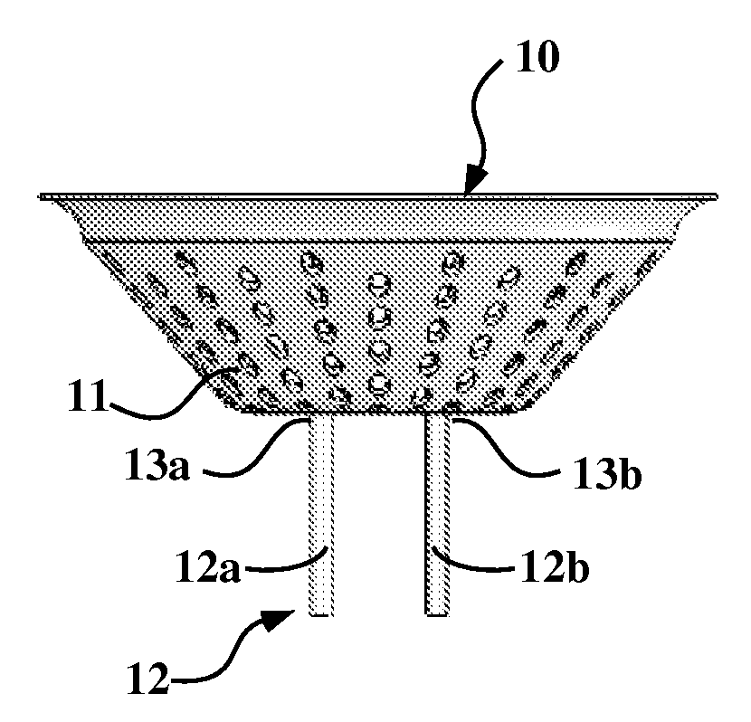
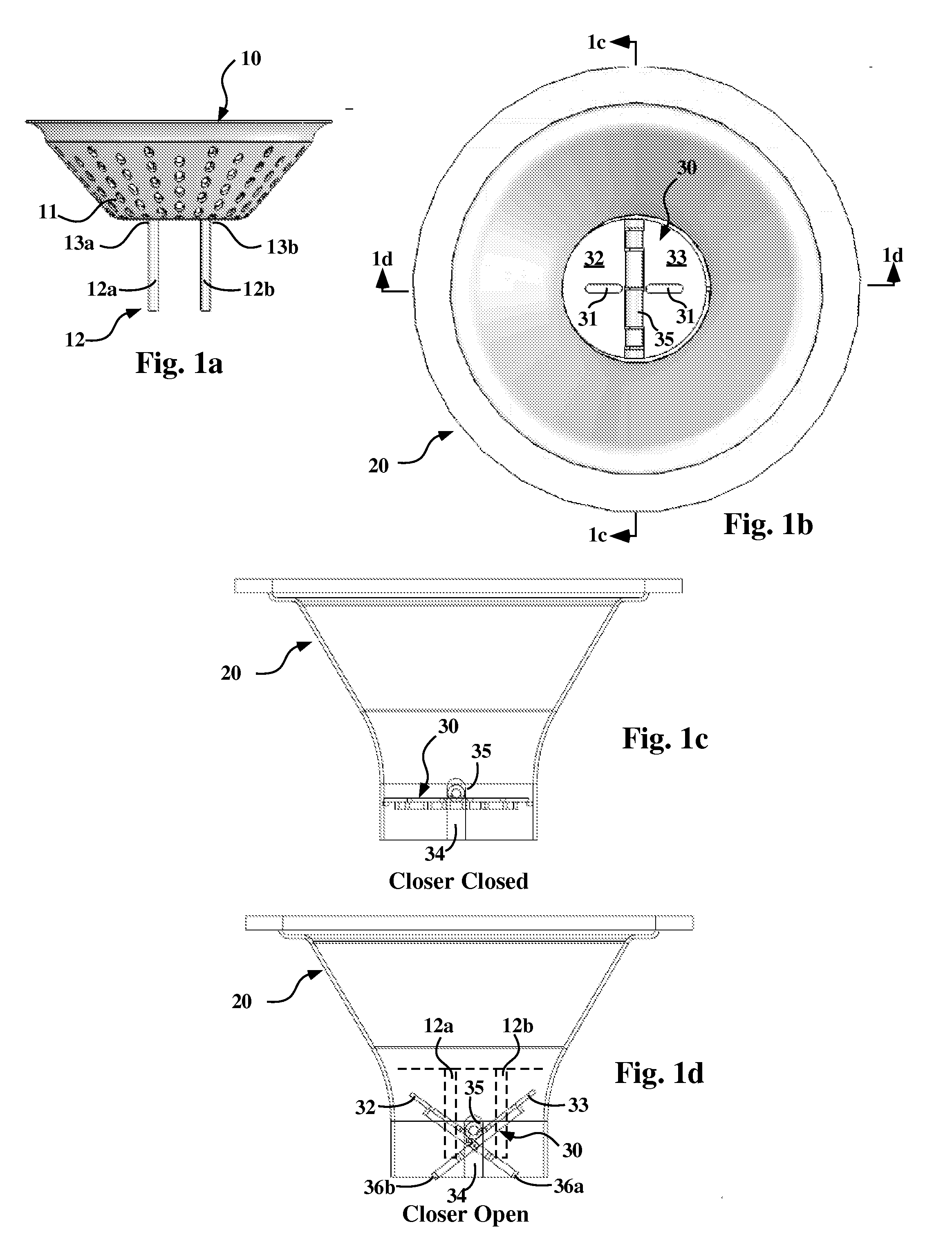
[0020]FIG. 1a illustrates a strainer basket 10 with straining portion 11 and an actuator 12 which controls the state of a closer mechanism on a drain. The actuator 12 is coupled to the straining portion 11. Actuator 12 includes pins 12a and 12b that are coupled to the straining portion 11 at welds 13a and 13b. The welds 13a and 13b can be polished to prevent sites that might harbor bacteria.

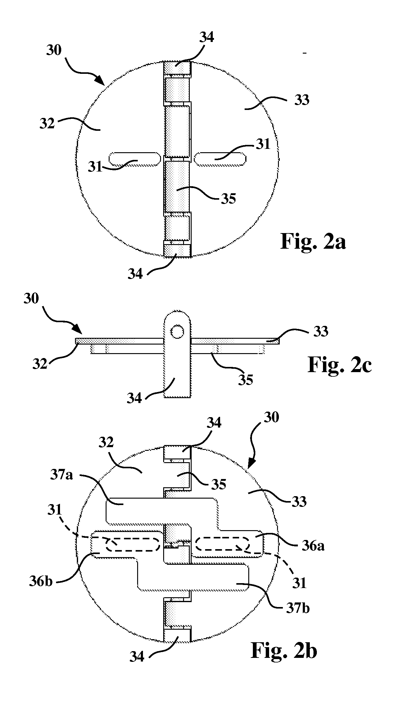
[0021]FIG. 1b illustrates a top view of a funnel drain 20 assembled with the drain closer 30 assembly in position at the bottom of the funnel drain cone. When the strainer 10 with actuator 12 is removed, the closer mechanism 30 closes (FIG. 1c), preventing unstrained water from flowing therethrough. When the pins 12a-b of actuator 12 engage with the drain closer mechanism 30 through slots 31, the closer mechanism 30 opens (FIG. 1d) to allow st...


PUM

PropertyMeasurementUnit
sizeaaaaaaaaaa
massaaaaaaaaaa
pressureaaaaaaaaaa

Abstract

Cleaning operations involving steam and flushing with water produce runoff that flows into drains installed in factory floors. Allowing bulky materials to flow into and plugging factory drains creates floor flooding conditions, production line shutdown and loss of time and money. These conditions can occur when strainer baskets are removed from drains. A drain facilitated with a drain closer prevents flow of bulky materials into drains and subsequent plugging. The drain closer is activated with a modified strainer basket such that removal of the basket closes the drain preventing inflow of bulky materials.

Description

CROSS-REFERENCE TO RELATED APPLICATIONS[0001]This application claims the benefit of the filing date of copending provisional application U.S. Ser. No. 60 / 979701, filed Oct. 12, 2007, entitled “STEEL DRAIN WITH AUTOMATIC CLOSER”, which is incorporated by reference herein.STATEMENT OF FEDERALLY SPONSORED RESEARCH OR DEVELOPMENT[0002]Not ApplicableBACKGROUND OF THE INVENTION[0003]1. Technical Field[0004]This invention relates in general to drains and, more particularly, to a drain which automatically closes when its strainer basket is removed.[0005]2. Description of the Related Art[0006]Equipment in commercial bakeries often requires periodic sanitation operations. Sanitation processes include cleaning with steam and flushing with water to remove the debris accumulated on the machines from the baking process. The flushed debris flows into floor drains and can include, along with the materials called “fines”, larger materials having substantial mass. Larger bulkier materials will plug t...

Claims


Application Information

Patent Timeline
Patent Type & Authority Applications(United States)
IPC IPC(8): C02F1/40C02F103/32
CPCE03C1/262E03F5/0407E03F5/0404
Inventor SHIPLEY, WILLIAMHELLER, SHELIAHENRY, JOHN
Owner EAST CREEK CORP
Why Eureka
Try Eureka