
Method for producing a composite rolling bearing

Inactive Publication Date: 2014-07-31
SCHAEFFLER TECH AG & CO KG
View PDF5 Cites 3 Cited by
  • Summary
  • Abstract
  • Description
  • Claims
  • Application Information

AI Technical Summary

Benefits of technology

[0012]The formation of the material overhangs of reserve material makes it possible to keep the forming forces low. In this context, the forming forces can be modified through the forming angle of the rollers on the feed cone. For example, the feed and slope of the rollers can be set in accordance with a radial va

Problems solved by technology

In this way, displacement or deformat

Method used


Image

  • Method for producing a composite rolling bearing
  • Method for producing a composite rolling bearing
  • Method for producing a composite rolling bearing

Examples


Example

DETAILED DESCRIPTION OF THE FIGURES

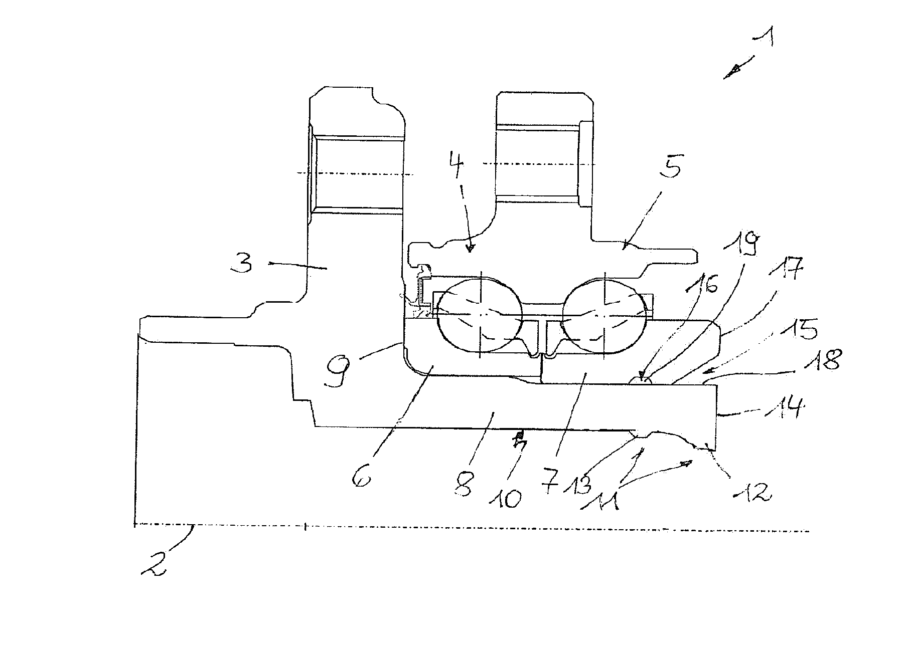
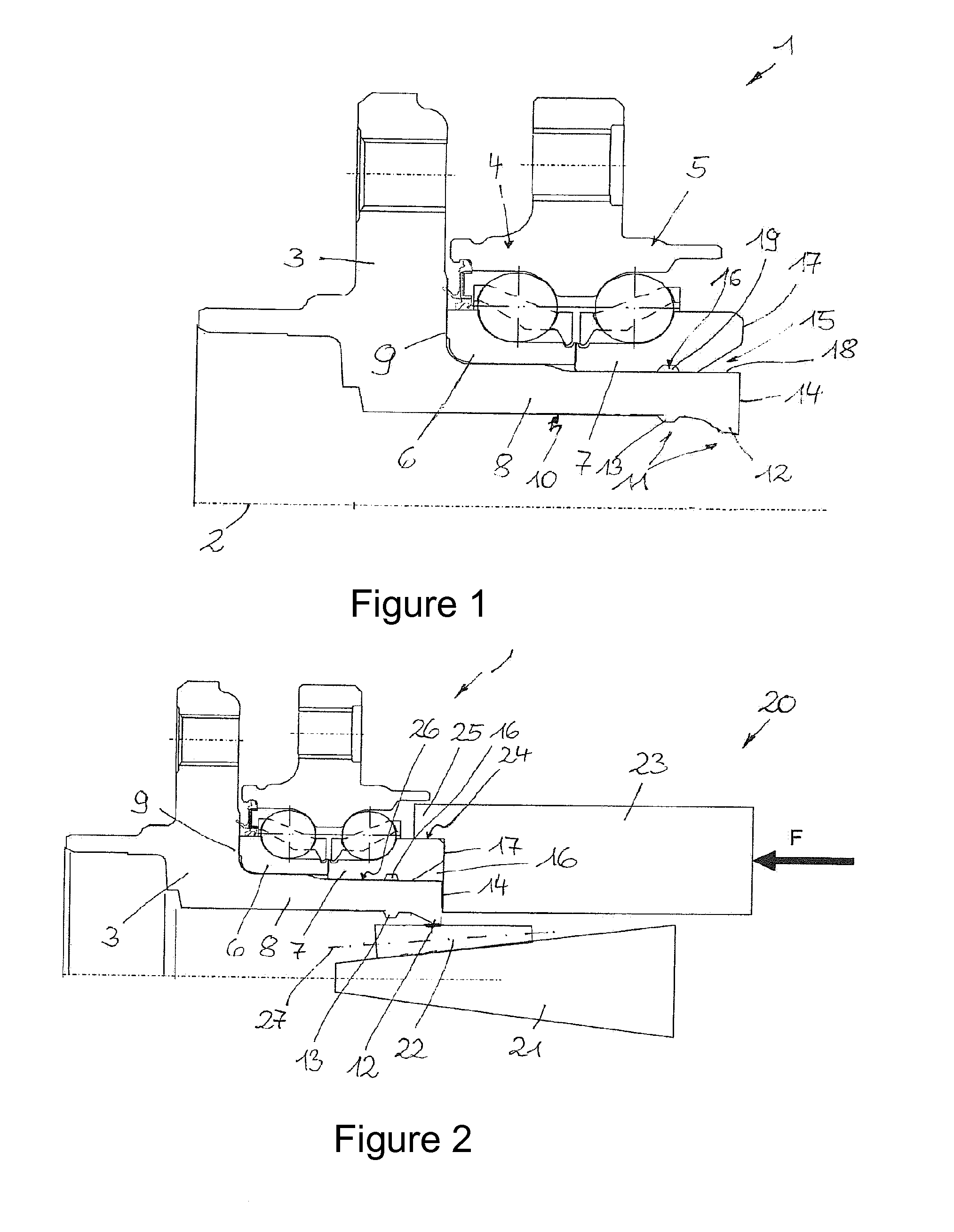
[0025]FIG. 1 shows a partial section through the composite rolling bearing 1 in unprocessed form arranged around the axis 2 of rotation. The bearing flange 3 accommodates two rolling bearings 4, 5, which are arranged axially adjacent to one another and the inner rings 6, 7 of which are mounted without play, by means of an interference fit, against the axial stop 9, on the flange part 8 arranged along and around the axis 2 of rotation.

[0026]The reserve material 11 in the form of the material overhangs 12, 13 is extended out of the cylindrical surface 10 radially inward and in a ring over the circumference of the inner circumference of the bearing flange 3. At the end 14 of the bearing flange 3, material overhang 12 has a substantially wedge shaped cross section which widens radially in the direction of the end 14. Material overhang 13 is at an axial distance from the end 14 in the direction of the axial stop 9.

[0027]Recessed formations 15, 16 comple...


PUM

PropertyMeasurementUnit
Forceaaaaaaaaaa
Widthaaaaaaaaaa
Distanceaaaaaaaaaa

Abstract

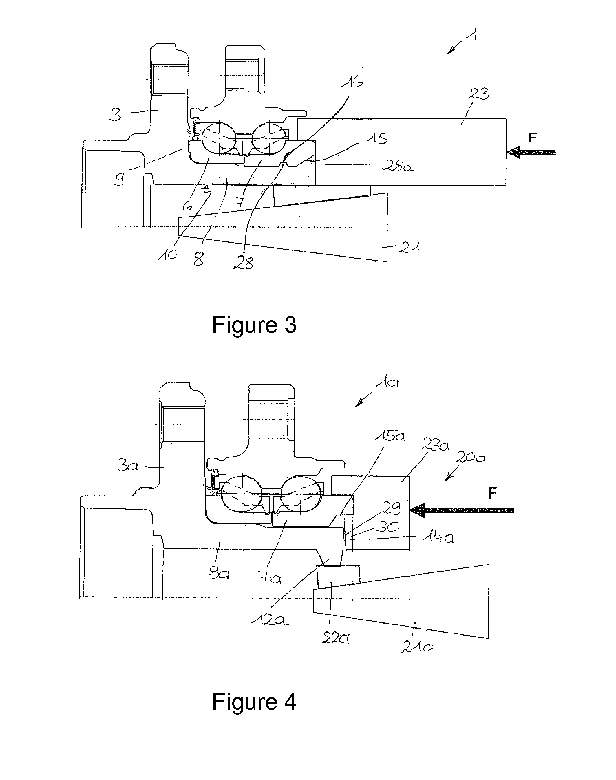
A method for producing a composite rolling bearing (1) having a bearing flange (3) and at least one rolling bearing (4, 5) held on the bearing flange (3) by an inner ring (6, 7). In order to be able to fix the inner ring (7) on the bearing flange (3) with axial preloading without expansion, the inner ring (7) is acted upon by a holding-down device (23) that radially holds down the inner ring (7) and is preloaded against the inner ring (7) by a regulated axial force (F), and, by way of an advancing cone (21) introduced radially on the inside axially into the bearing flange (3), material (11) present on the bearing flange (3) is displaced radially towards the outside into a recessed formation (15, 16) in the inner ring (7).

Description

FIELD OF THE INVENTION[0001]A method for producing a composite rolling bearing having a bearing flange and at least one rolling bearing held on the bearing flange by means of an inner ring.BACKGROUND OF THE INVENTION[0002]Composite rolling bearings of the type in question are used as wheel bearings in motor vehicles, for example, wherein the bearing flange accommodates at least one, preferably two, rolling bearings arranged axially adjacent to one another and having inner rings. In this arrangement, the inner rings are mounted on the bearing flange under an axial preload. DE 10 2008 064 155 A1 discloses a rotary forming method for producing a riveting collar on the bearing flange, in which a riveting collar is obtained from a flange part extending axially along the axis of rotation of the rolling bearings by forming the end face radially. In this process, rollers of a feed cone, which are set at an angle relative to the axis of rotation, form the riveting collar. Compared with conve...

Claims


Application Information

Patent Timeline
IPC IPC(8): F16C43/08
CPCF16C43/086B21H1/12F16C35/063F16C19/185F16C33/586F16C2326/02F16C2229/00Y10T29/49682
Inventor KAISER, ANDREASNIEBLING, PETERLANGER, ROLANDEICHELMANN, FRANK
Owner SCHAEFFLER TECH AG & CO KG
Learn More