Light emitting module, lighting apparatus, and lighting fixture

a technology of light emitting modules and lighting fixtures, applied in the direction of basic electric elements, electrical equipment, semiconductor devices, etc., can solve the problems of difficulty in obtaining illumination light of a desired color

Inactive Publication Date: 2014-07-31
PANASONIC INTELLECTUAL PROPERTY MANAGEMENT CO LTD
View PDF7 Cites 24 Cited by
  • Summary
  • Abstract
  • Description
  • Claims
  • Application Information

AI Technical Summary

Benefits of technology

[0018]According to the light emitting module relating to one aspect of the present invention, the optical member, which is formed from a translucent material having a refractive index higher than air, is provided between the first light emitting part and the second light emitting part. Also, the side surface of the optical member includes the first region facing the first sealing member and the second region facing the second sealing member. The first region is at least partially in contact with the surface of the first sealing member, and the second region is at least partially in contact with t

Problems solved by technology

If such different types of phosphors mix with each other, hue of light emitted from the light emitting part

Method used


Image

  • Light emitting module, lighting apparatus, and lighting fixture
  • Light emitting module, lighting apparatus, and lighting fixture
  • Light emitting module, lighting apparatus, and lighting fixture

Examples


embodiment

[0037]The following describes a light emitting module, a lighting apparatus, and a lighting fixture relating to one aspect of the present invention, with reference to the drawings.

[0038]

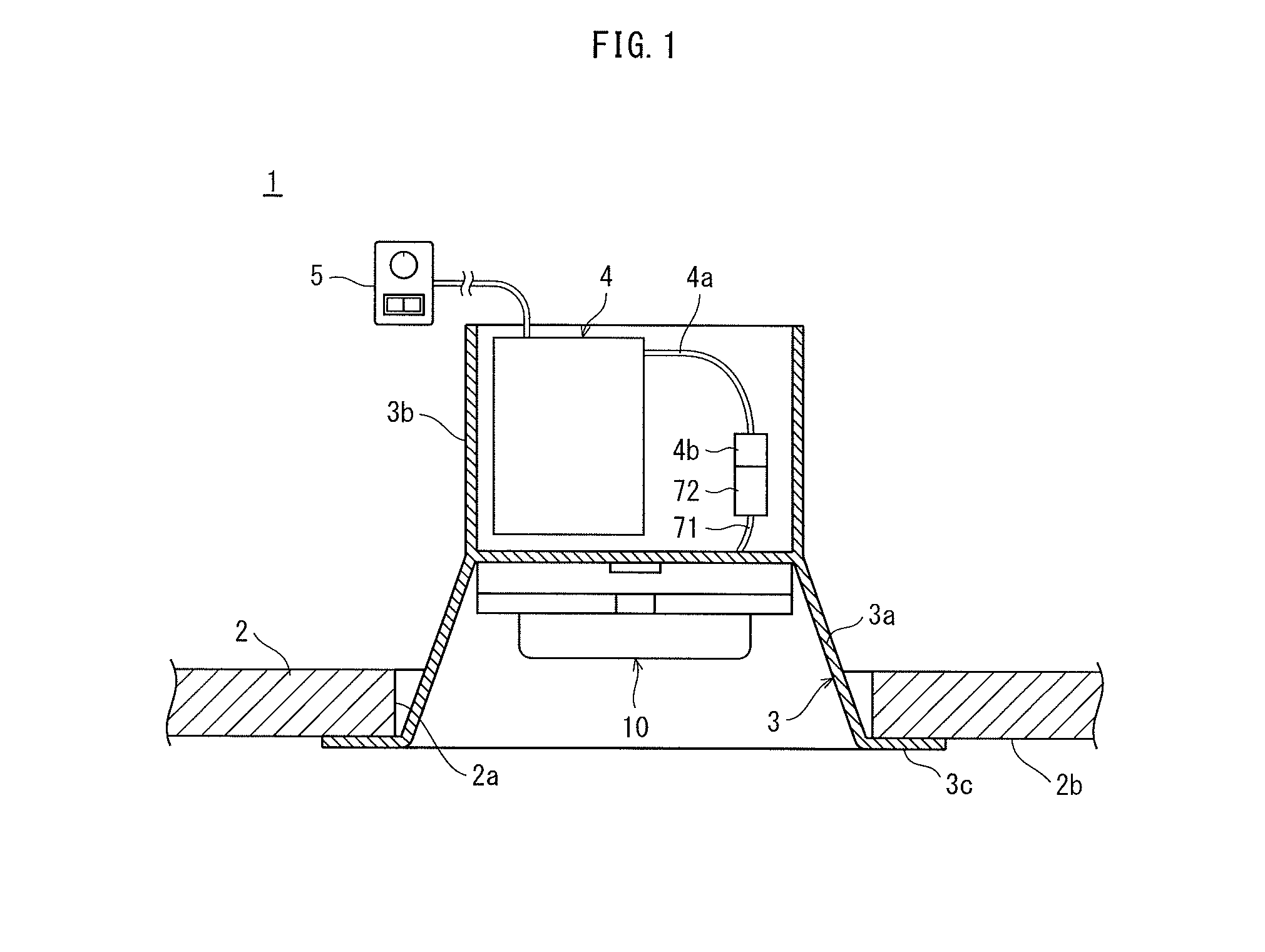
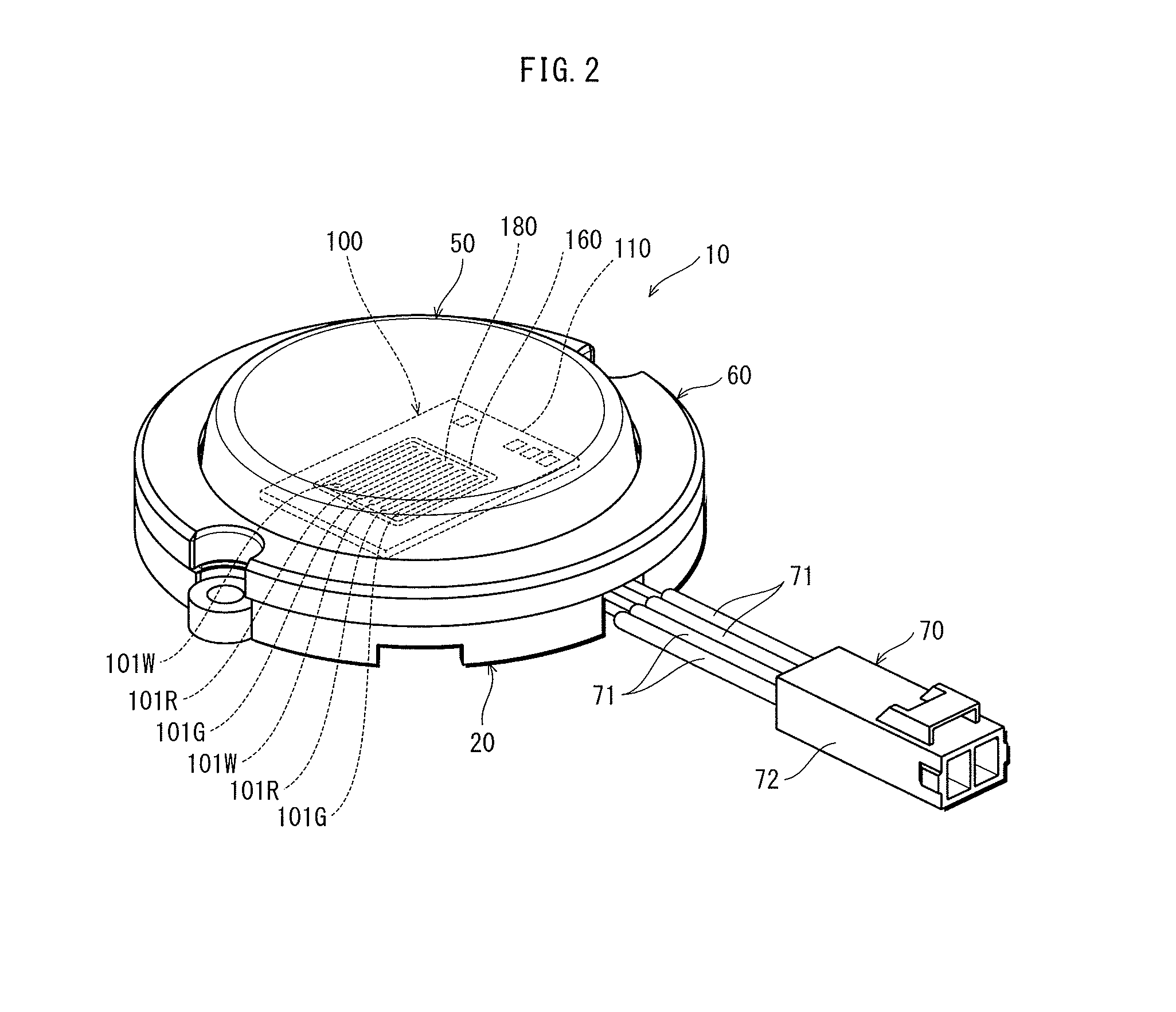
[0039]FIG. 1 is a cross-sectional view showing the lighting fixture relating to the one aspect of the present invention. FIG. 2 is a perspective view showing the lighting apparatus relating to the one aspect of the present invention. As shown in FIG. 1, a lighting fixture 1 relating to the one aspect of the present invention is for example a downlight which is embedded into the ceiling 2 to be attached to the ceiling 2, and includes a lighting appliance 3, a circuit unit 4, a dimming unit 5, and further includes a lighting apparatus 10 shown in FIG. 2.

[0040]The lighting appliance 3 is for example metal, and includes a lamp housing 3a, and a circuit housing 3b and an outer flange 3c. The lamp housing 3a is for example cylindrical and bottomed. The lighting apparatus 10 is detachably attached inside th...


PUM


Abstract

A light emitting module is provided in which color unevenness of illumination light is difficult to occur. An optical member formed from a translucent material having a refractive index higher than air is interposed between a first light emitting part and a second light emitting part. A side surface of the optical member has a region facing a first sealing member, and the region is at least partially in contact with a surface of the first sealing member. The side surface of the optical member has a region facing a second sealing member, and the region is at least partially in contact with a surface of the second sealing member. In plan view, an upper surface of the optical member does not substantially overlap either of an upper surface of a first light emitting element or an upper surface of a second light emitting element.

Description

[0001]This application is based on application No. 2013-013613 filed in Japan, the contents of which are hereby incorporated by reference.TECHNICAL FIELD[0002]The present invention relates to a light emitting module including a light emitting part using light emitting elements such as LEDs (Light Emitting Diodes), a lighting apparatus, and a lighting fixture, and particularly to an art of reducing color unevenness of illumination light in mixed light illumination with use of light emitting parts of two or more types of different colors.BACKGROUND ART[0003]Conventionally, there has been proposed mixed light illumination with use of light emitting parts of two or more types of different colors and mixing light emitted from the light emitting parts to obtain illumination light of a desired color (Patent Literature 1). One example of such mixed light illumination is a light emitting module that includes a white light emitting part that emits white light, a red light emitting part that e...

Claims


Application Information

Patent Timeline
IPC IPC(8): H01L27/15H01L33/58
CPCH01L33/58H01L27/15H01L25/0753H01L33/54H01L33/56H01L2924/0002H01L2924/00
Inventor YAMAMOTO, YUUYAHIRAMATSU, KOHJI
Owner PANASONIC INTELLECTUAL PROPERTY MANAGEMENT CO LTD
Why Eureka
Try Eureka