
Production facility comprising a transport system for processing elongated products, in particular wind turbine blades, with elongated mould assemblies

Active Publication Date: 2014-08-07
VESTAS WIND SYST AS
View PDF31 Cites 7 Cited by
  • Summary
  • Abstract
  • Description
  • Claims
  • Application Information

AI Technical Summary

Benefits of technology

The inventive production facility includes a transport system that allows for the proper positioning of the movable parts along the entire length of the mold assemblies. This allows for changing the position of the elongated support member, which can be beneficial during the production process. The facility also includes a stationary support member system that allows for the rotation of the mold assembly without interference. The system includes multiple support members and gaps between them can be bridged by the movable part. The technical effects include improved accessibility and efficiency in the production process.

Problems solved by technology

In particular, when a high degree of flexibility in operating a robot system on the basis of a transport system is required, as discussed above, typically the transport system comprises at least one centre rail positioned laterally between the movable and non-movable mould assemblies, wherein, however, the central position of this rail may significantly interfere with the rotational movement of the movable mould assembly.

Method used


Image

  • Production facility comprising a transport system for processing elongated products, in particular wind turbine blades, with elongated mould assemblies
  • Production facility comprising a transport system for processing elongated products, in particular wind turbine blades, with elongated mould assemblies
  • Production facility comprising a transport system for processing elongated products, in particular wind turbine blades, with elongated mould assemblies

Examples


Embodiment Construction

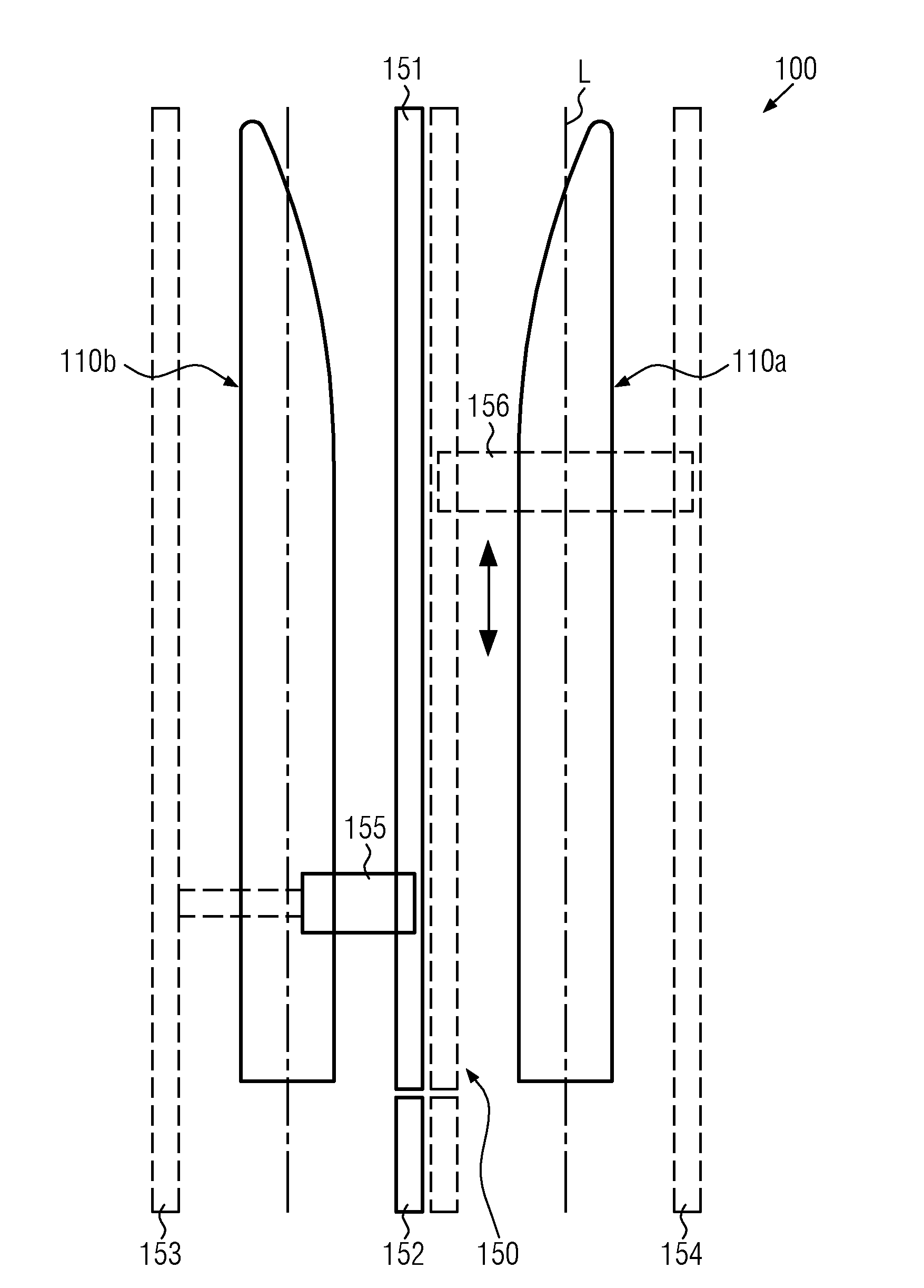
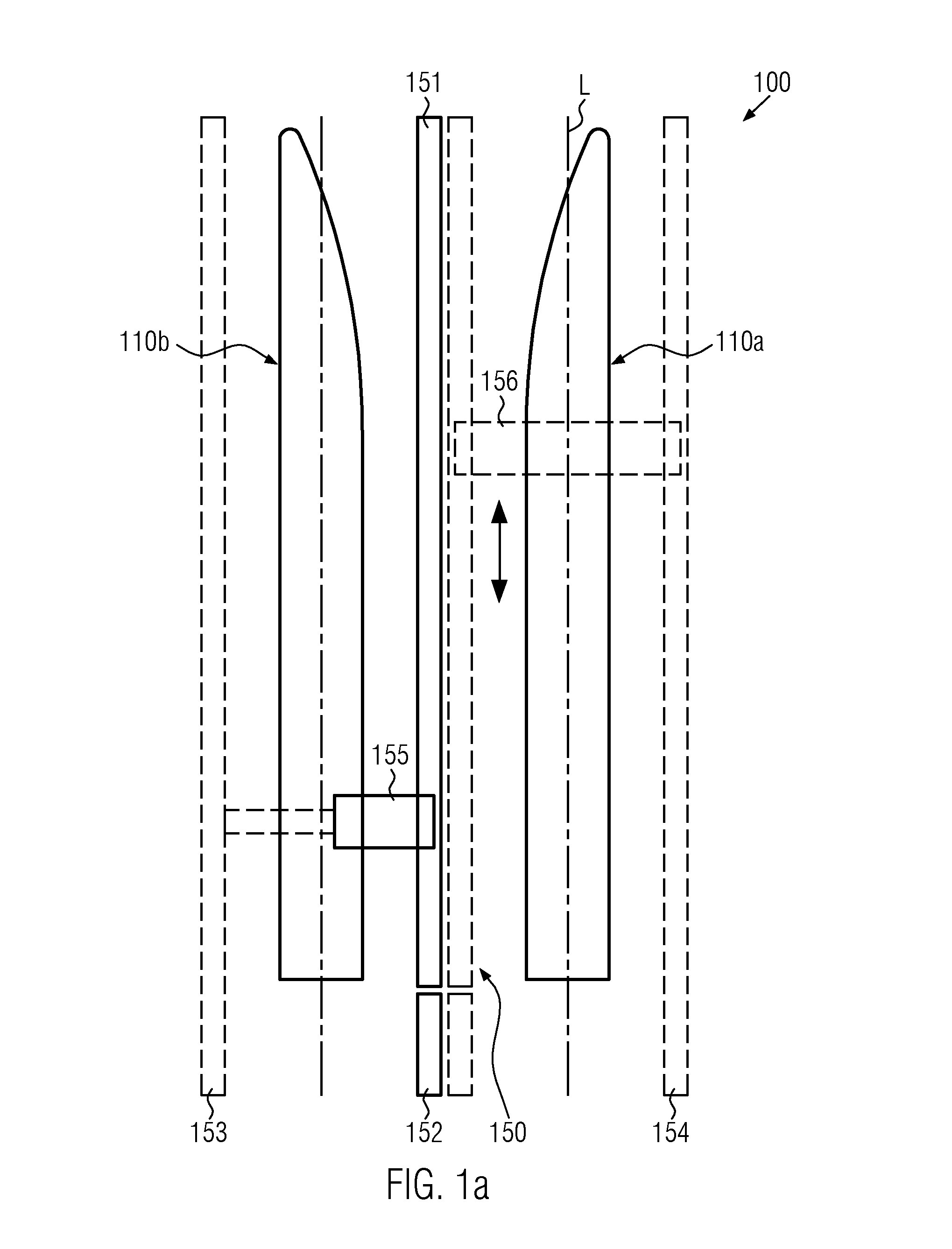
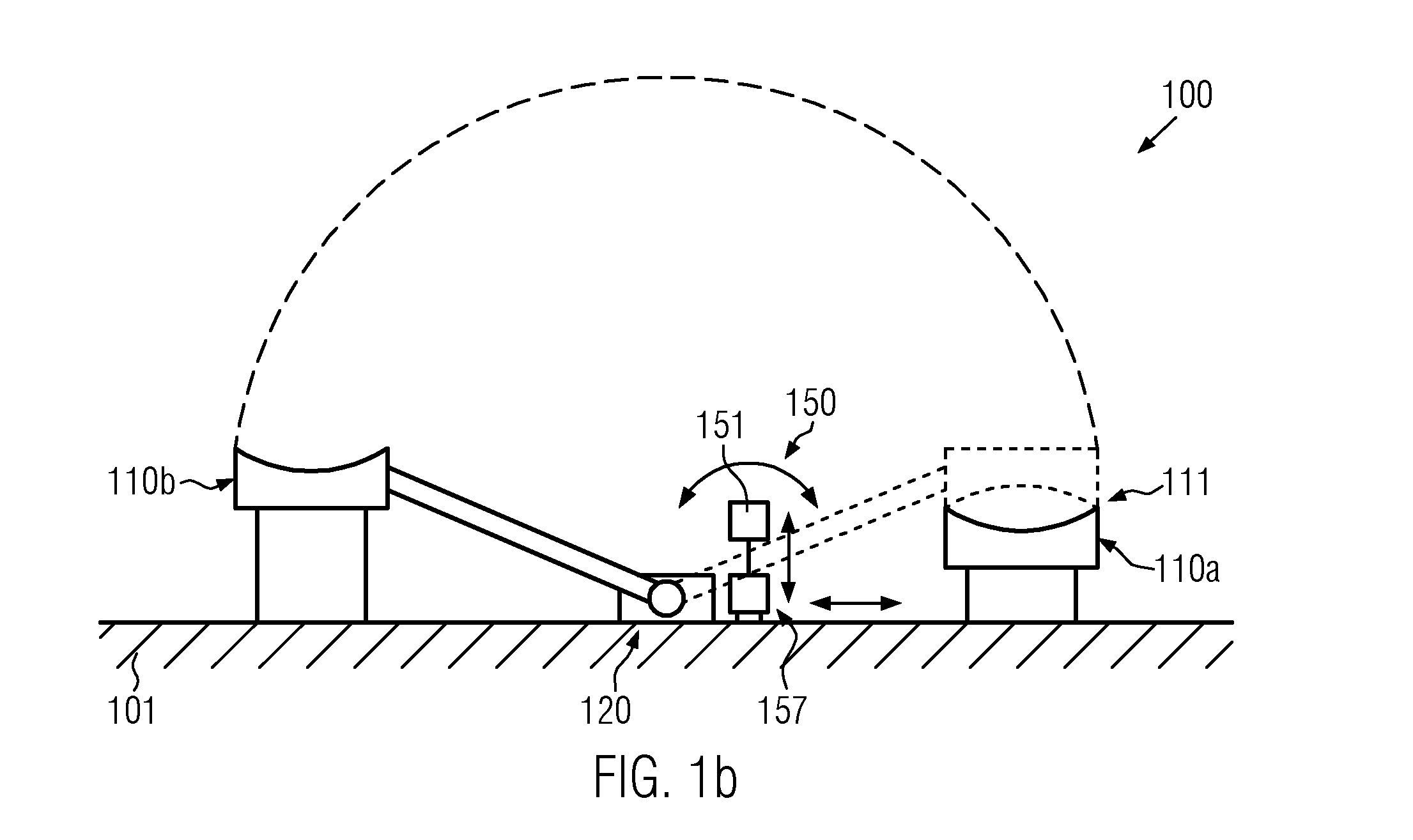
[0073]A first version of the present invention will now be described in more detail with reference to the accompanying drawings with FIGS. 1a to 5b, wherein generally like components are denoted by the same reference numbers except for the first digit, which generally refers to the corresponding figure, in which an embodiment is illustrated. Thus, it should be appreciated that the description of components having the same reference number except for the first digit may be omitted, if appropriate, while it is nevertheless to be understood that the component in question may have one or more of the features of corresponding components referred to in previously described or later-described embodiments.

[0074]FIG. 1a schematically illustrates a top view of a production facility 100, in which are installed a first mould assembly 110a and a second mould assembly 110b, which are arranged in parallel to each other. The first and second mould assemblies 110a, 110b are elongated mould assemblie...


PUM

PropertyMeasurementUnit
Lengthaaaaaaaaaa
Shapeaaaaaaaaaa
Surface areaaaaaaaaaaa

Abstract

The present invention relates to a production facility (100, 200, 300, 400, 500) for forming elongated products, in particular wind turbine blades, wherein elongated mould assemblies (110a, 110b, 210a, 210b, 310a, 310b, 410a, 410b, 510a, 510b) may be accessed on the basis of an appropriate transport system (150, 250, 350, 450, 550) comprising at least one support member (251a-h, 151, 251, 351, 451, 551) laterally positioned between the elongated mould assemblies. The support member (251a-h, 151, 251, 351, 451, 551) is positioned so as to enable a rotational movement of an arm (121a, 121b, 221a) or is configured to change position or comprises a rotatable carrier element (259). For example, an elongated support member (151, 251, 351, 451, 551) may be positioned in a non-interference position, in which one or both mould assemblies can be moved into a position so as to form a composite mould assembly.

Description

TECHNICAL FIELD AND BACKGROUND[0001]Generally, the present invention relates to a production facility with a transport system, wherein elongated products, in particular wind turbine blades, are formed by using moulds that extend along the length of the elongated product and by combining the moulds to form the complete elongated product.[0002]Elongated products, such as wind turbine blades, are frequently formed on the basis of fibre reinforced polymer materials, wherein a technique is frequently used, in which a first half of the elongated product is formed by applying layer after layer in one of the moulds and at the same time preparing the second half of the elongated product layer after layer in the second mould and finally combining the two moulds so as to join the two halves of the elongated product. Typically, the two halves have to be prepared on the basis of a specific process strategy with high precision, in particular when considering wind turbine blades, so that there is ...

Claims


Application Information

Patent Timeline
IPC IPC(8): F01D5/14
CPCF05B2230/21F01D5/147B29C33/26F03D1/0675B29L2031/085B29C70/38B29C31/04Y10T29/49336Y10T29/37Y02E10/72Y02P70/50
Inventor BECH, ANTONTAPIA, RAUL GARCIAPETERSEN, AKSEL
Owner VESTAS WIND SYST AS
Learn More