
Booster bicycle pedal

A technology for assisting bicycles and pedals, which is applied to bicycle accessories, bicycle auxiliary equipment, vehicle components, etc. It can solve the problems that the stirrups on both sides cannot be symmetrical, meet the comfort requirements of the motor vehicle pedals, and shorten the pedals to achieve superior continuity. Effect

Inactive Publication Date: 2006-09-20
季银
View PDF1 Cites 3 Cited by
  • Summary
  • Abstract
  • Description
  • Claims
  • Application Information

AI Technical Summary

Problems solved by technology

The patent No. CN94222761.1 is the technical scheme of the bicycle adjustable variable speed crank. Subjectively, it shortens the crank to a certain length and at the same time must keep a certain crank length to ensure the pedal to adjust the riding speed. The distance is close, but this closeness is only caused by the pedal driving state and is limited. It cannot make the two sides of the stirrups symmetrical and meet the comfort requirements of the motor vehicle pedals.

Method used


Image

  • Booster bicycle pedal
  • Booster bicycle pedal
  • Booster bicycle pedal

Examples


Embodiment Construction

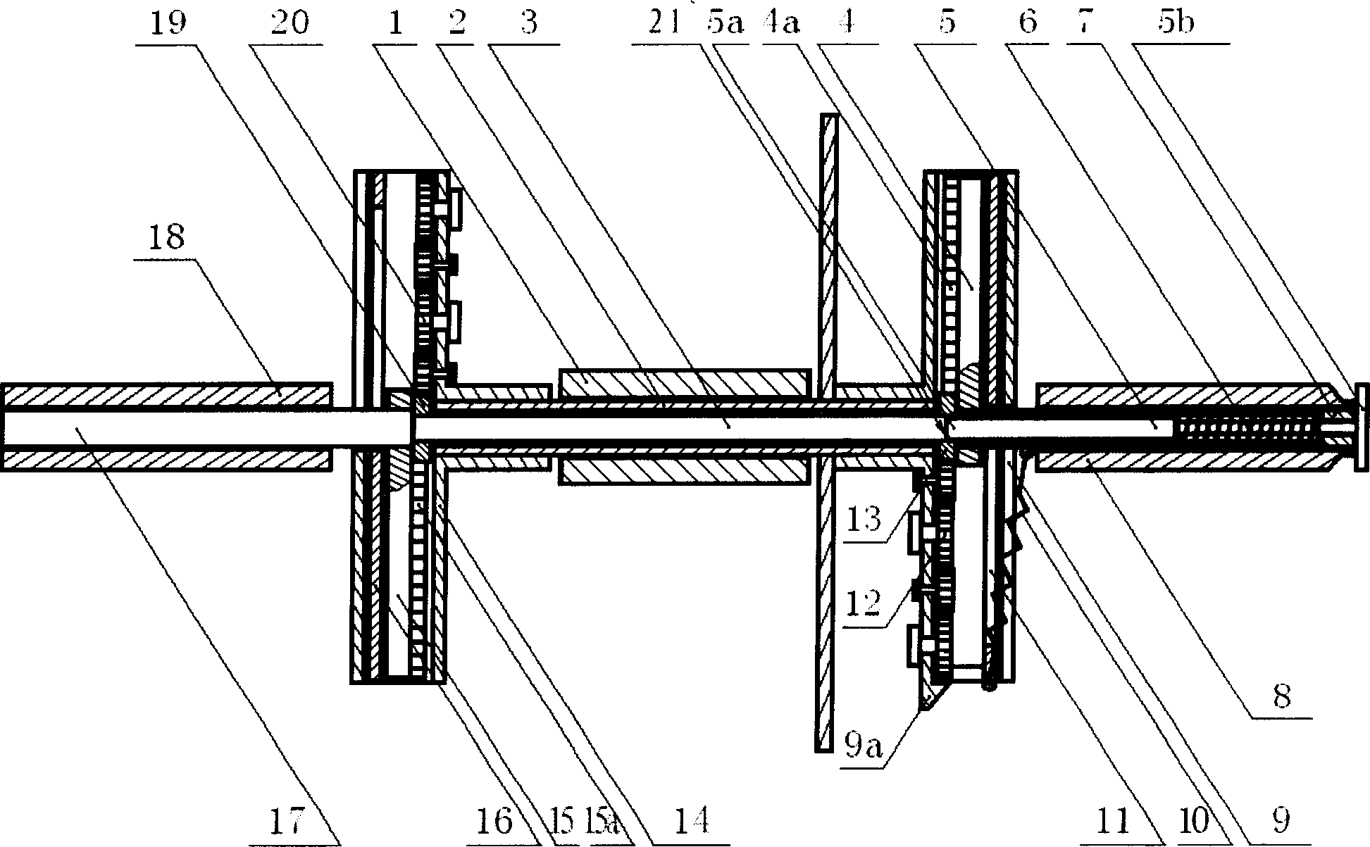
[0023] like figure 1 As shown, the power-assisted bicycle pedal of the present invention is composed of a central shaft cylinder 1, a central shaft 2 provided with a mandrel 3, a crank main body part that is provided with a handle moving sliders 4, 15, that is, a handle body 11, 16, and a slider 4 , 15 are fixedly connected with stirrup shafts 7, 17 and stirrup shafts 8, 18. The inner end of the crank, namely the handle base 9, 14 is fixedly connected with the central shaft 2, and the stirrup shafts 8, 18 are movable with the stirrup shafts 7, 17. connect.

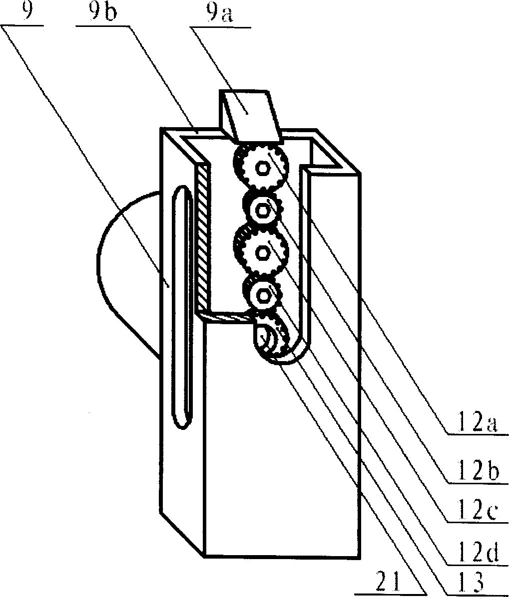
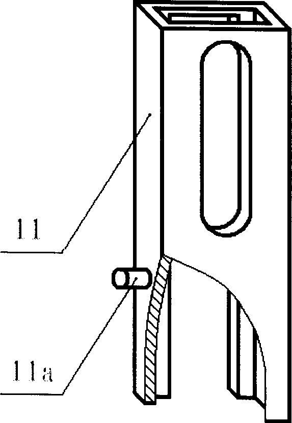
[0024] like figure 1 , 2 , 3, 5, and 6, the handle body 11, 16 is separated from the handle base 9, 14 and plugged in, the handle base 9, 14 is set as a slideway structure that can pass through the handle, and the handle body 11, 16 is provided with a handle Base 9,14, the outer end of handle body 11,16 can stretch out handle base 9,14, and handle base 9,14 plays a stabilizing effect to handle body 11,16 sliding.

[00...


PUM


Abstract

A pedal structure for boosted bicycle is composed of a crank base, crank body passing through said axle base, a slide block on crank body and with active rack bar, a mandrel with driven gears at its both ends, drive gear chain on said crank base, and at least one supporting mechanism for fixating the crank consisting of slide block, crank base and crank body. It has high switching speed.

Description

technical field [0001] The invention relates to the technical field of bicycle pedals, in particular to a pedal of a moped. The moped is a multifunctional power-assisted bicycle with human drive, power drive or both human drive and power drive. Background technique [0002] Power-assisted bicycles are easy to use and have become an important means of transportation that is becoming increasingly popular. When manual drive or manual drive and power drive are used together, the feet move up and down around the central axis on both sides of the car body in a circular motion; but when the power drive is used, the feet are in a rest state, and the feet should be placed symmetrically on the car body. The position of the central axis on both sides is in line with the principles of human mechanics engineering; in summary, when the car body is driven by human power, the stirrups on both sides of the car body are staggered up and down, left and right, and when the power is driven, the...

Claims


Application Information

Patent Timeline
Patent Type & Authority Applications(China)
IPC IPC(8): B62M3/00B62M3/08B62J23/00
Inventor 季银
Owner 季银
Learn More