Manometer

a manometer and manometer technology, applied in the field of manometers, can solve the problems of inability to protect the safety range of the manometer, the inability to use protective means, and the inability to keep the manometer in the safety rang

Active Publication Date: 2014-08-07
CHOU WEN SAN
View PDF7 Cites 9 Cited by
  • Summary
  • Abstract
  • Description
  • Claims
  • Application Information

AI Technical Summary

Benefits of technology

[0004]Accordingly, the primary object of the present invention is to provide a manometer, which comprises a manometer body accommodating a plunger, a cap mount, a primary box spring and an auxiliary box spring. By means of the primary box spring and auxiliary box spring function as overall air pressure reflection in combination of coarse air pressure variation responded by the primary box spring and fine air pressure variation responded by the auxiliary box spring the value of the air pressure can be precisely measured.

Problems solved by technology

However, there are some drawbacks in foregoing conventional manometers.
Firstly, for displaying pressure value measured, both of the electronic manometer and mechanical manometer involve too many components with complicated structure.
Secondly, for air pressure in the manometer, there is no protective means to keep it in safety range.

Method used


Image

  • Manometer
  • Manometer
  • Manometer

Examples


Embodiment Construction

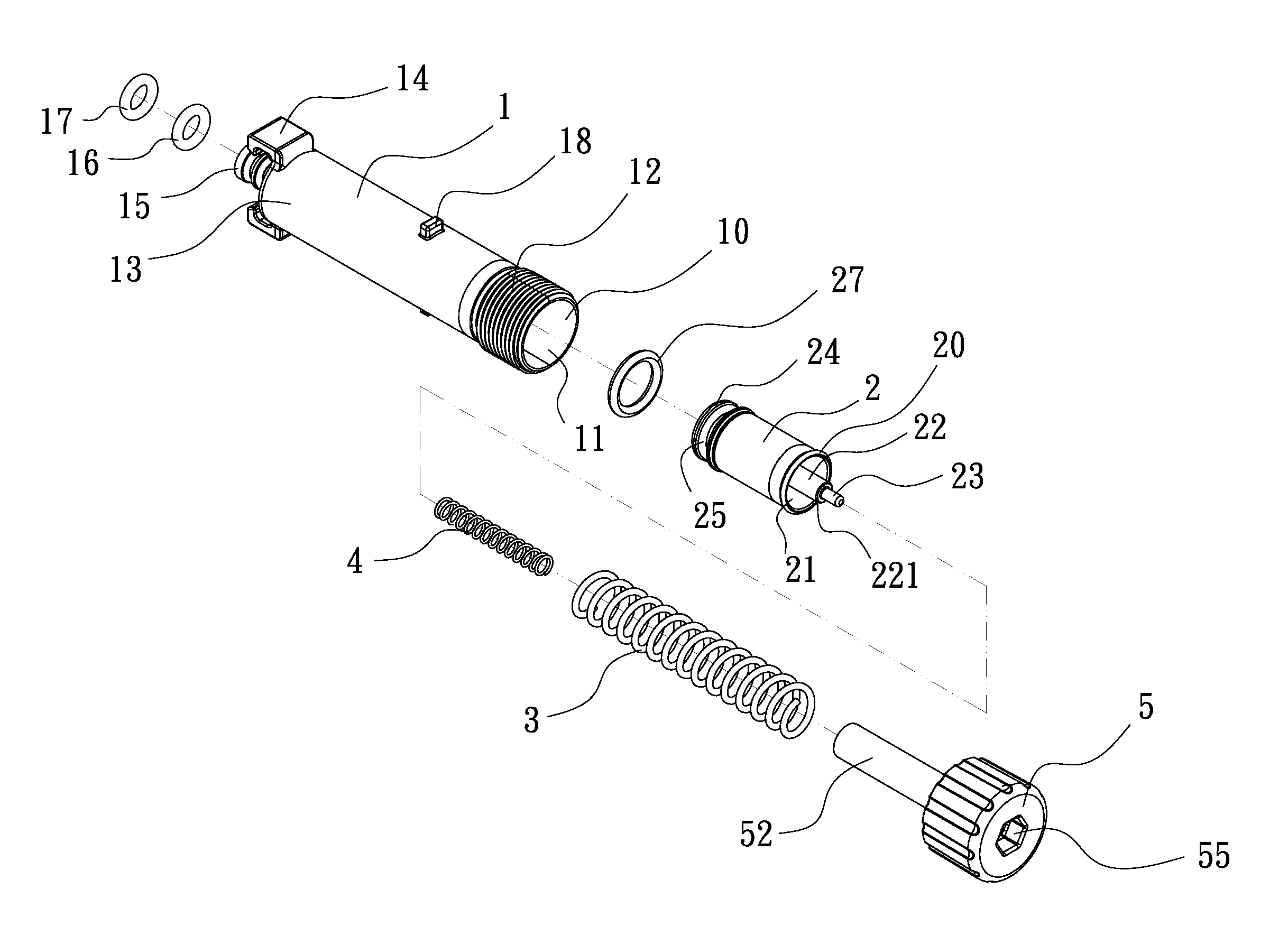
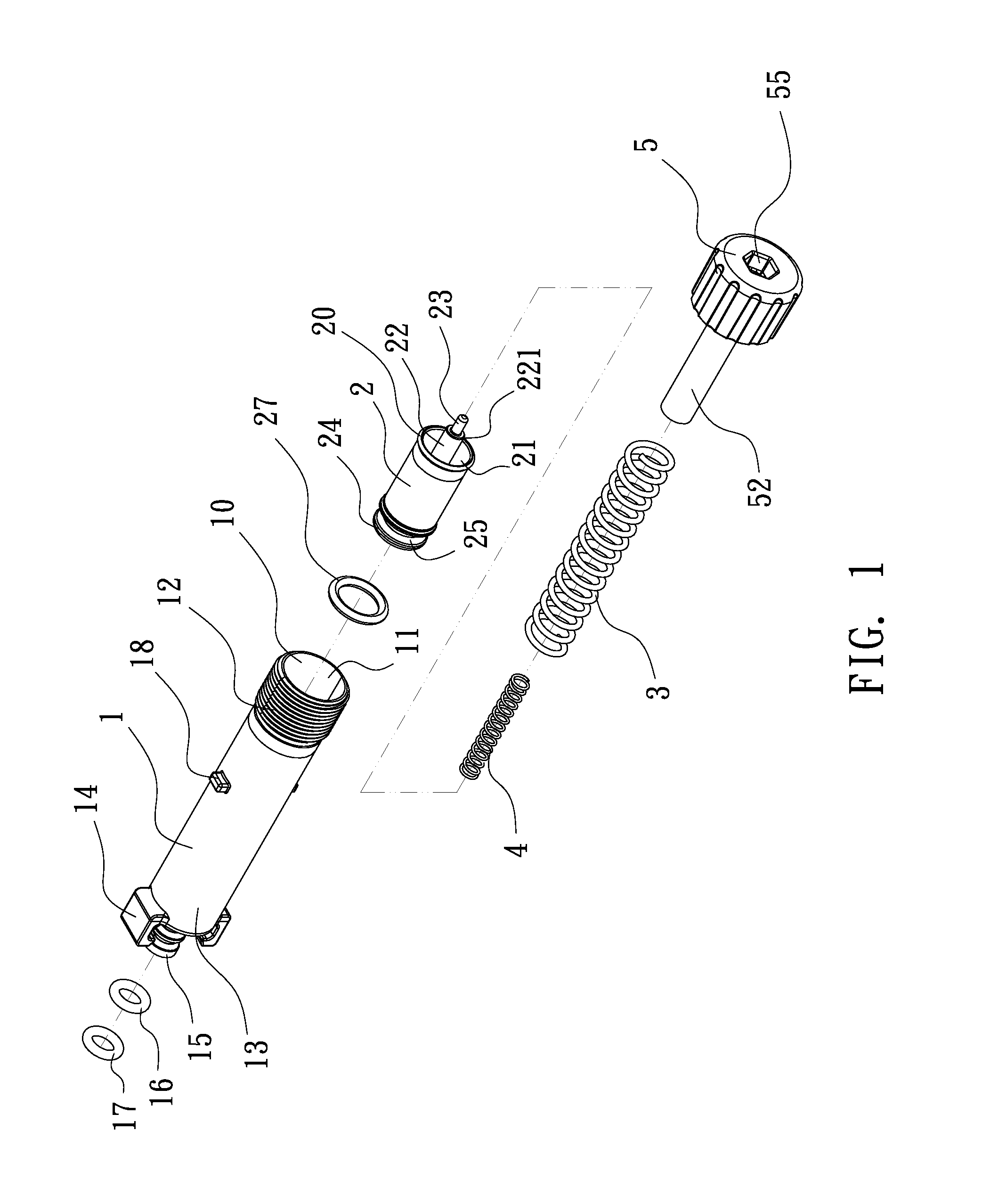
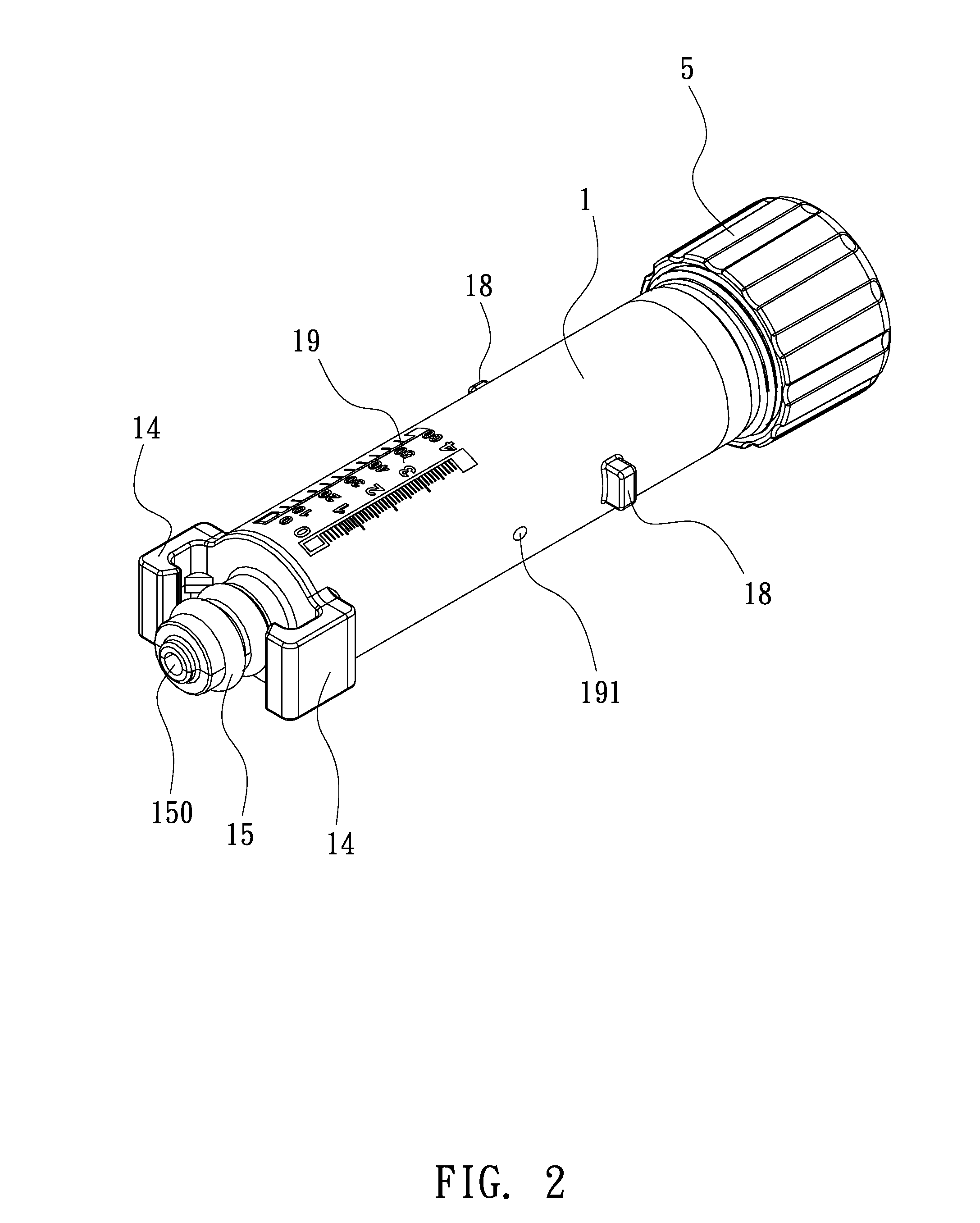
[0016]Please refer to FIGS. 1 through 4, which show the first exemplary preferred embodiment for a manometer of the present invention. The manometer of the present invention comprises a manometer body 1, a plunger 2, a cap mount 5, a primary box spring 3 and an auxiliary box spring 4, wherein said manometer body 1, which is a transparent cylinder with an indicating scale with graduated markings of pressure units 19 on the peripheral and an internal cylindrical cavity 11, includes a round head-end opening 10 with peripheral male thread 12, a round breech 13 having a centrally protruded adaptor 15 with a central internal longitudinal passage 150 and two separated peripheral O-ring 16 and 17, a pair of docking clamps 14, a pair of anchoring lugs 18 and a safety vent 191, wherein the pair docking clamps 14 are symmetrically disposed on the peripheral of the round breech 13, and the pair anchoring lugs 18 are symmetrically disposed on the peripheral of manometer body 1 at suitable middle...


PUM

PropertyMeasurementUnit
pressureaaaaaaaaaa
air pressureaaaaaaaaaa
transparentaaaaaaaaaa

Abstract

A manometer comprises a manometer body with an indicating scale with graduated markings of pressure units and a safety vent, a plunger with a annular groove and a tinted O-ring a cap mount, a primary box spring and an auxiliary box spring. By means of the tinted O-ring and the indicating scale with graduated markings of pressure units, the manometer innovatively functions as indication of air pressure measured. By means of the primary box spring and auxiliary box spring, the manometer precisely measures overall air pressure in combination of coarse air pressure variation responded by the primary box spring and fine air pressure variation responded by the auxiliary box spring. By means of the safety vent disposed on the peripheral of manometer body and the tinted O-ring on the plunger, the manometer provides a safety proactive means for input compressed air.

Description

TECHNICAL FIELD OF THE INVENTION[0001]The present invention relates to a manometer, particularly for one having primary box spring with auxiliary box spring, safety vent with tinted O-ring and indicating scale with graduated markings.BACKGROUND OF THE INVENTION[0002]A manometer is also called pressure meter or pressure gauge. Currently, conventional manometers can be roughly classified into two categories as electronic type and mechanical type. The electronic manometer typically integrates a pressure sensor and related electronic components to measure and display pressure value measured for example as Taiwan (ROC) patent application in number of TW093124608. Most mechanical manometers are adapted from Bourdon gauge, which basically integrates a Bourdon tube, a pivot with a pivot pin, a lever, a sector gear with gear train, an indicator needle and a hair spring to measure and display pressure value measured for example as Taiwan (ROC) patent application in number of TW088203528. Othe...

Claims


Application Information

Patent Timeline
Patent Type & Authority Applications(United States)
IPC IPC(8): G01L7/16
CPCG01L7/166G01L7/163G01L7/16G01L19/08
Inventor CHOU, WEN-SAN
Owner CHOU WEN SAN
Why Eureka
Try Eureka